


Serpentine Gallery Pavilion 2013
Introduction
Temporary structures for the Serpentine Gallery, one of the most anticipated events in the cultural sphere, corresponded in 2013 the Japanese architect Sou Fujimoto, and awarded by other projects and the youngest to accept the invitation to design such a structure in the 13 years since the event function.
In previous flags renowned architects participated, including Herzog & de Meuron in collaboration with Ai Weiwei (2012 ), Frank Gehry (2008 ), Oscar Niemeyer (2003 ) or Zaha Hadid who had to structure opening in 2000. Fujimoto ‘s third Japanese architect who accepts the invitation to design a temporary pavilion for the Serpentine Gallery, you antecederieon Toyo Ito (2002 ) and Kazuyo Sejima&Ryue Nishizawaof SANAA in 2009.
The Serpentine Gallery Pavilion 2013 designed by Sou Fujimoto remained open from June 8 to October 20, 2013.
Location
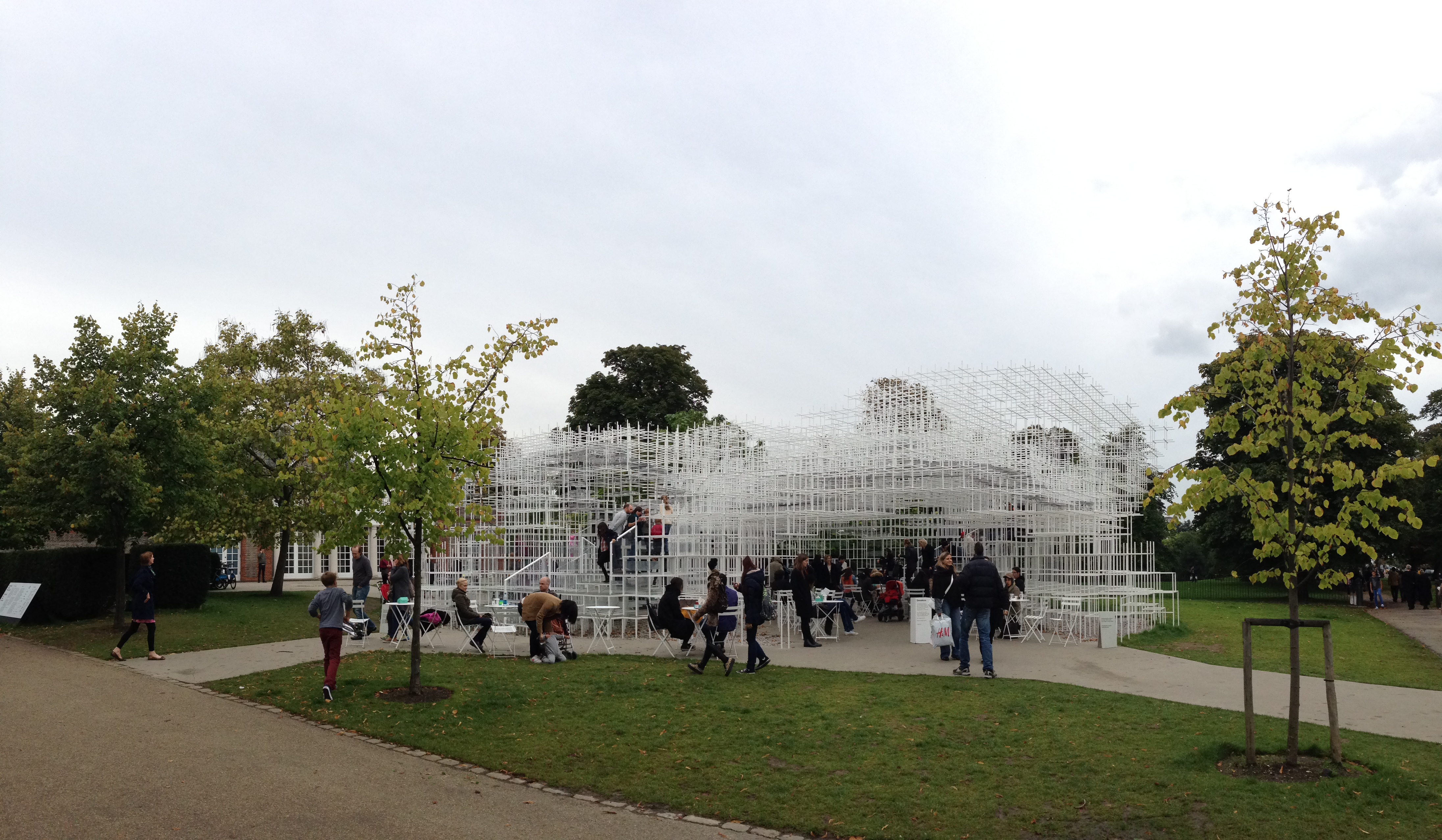
The Pavilion was located, as every year, in the garden of the Serpentine Gallery, Kensington Gardens opposite the east wing, London W2 3XA, England, UK.
Concept

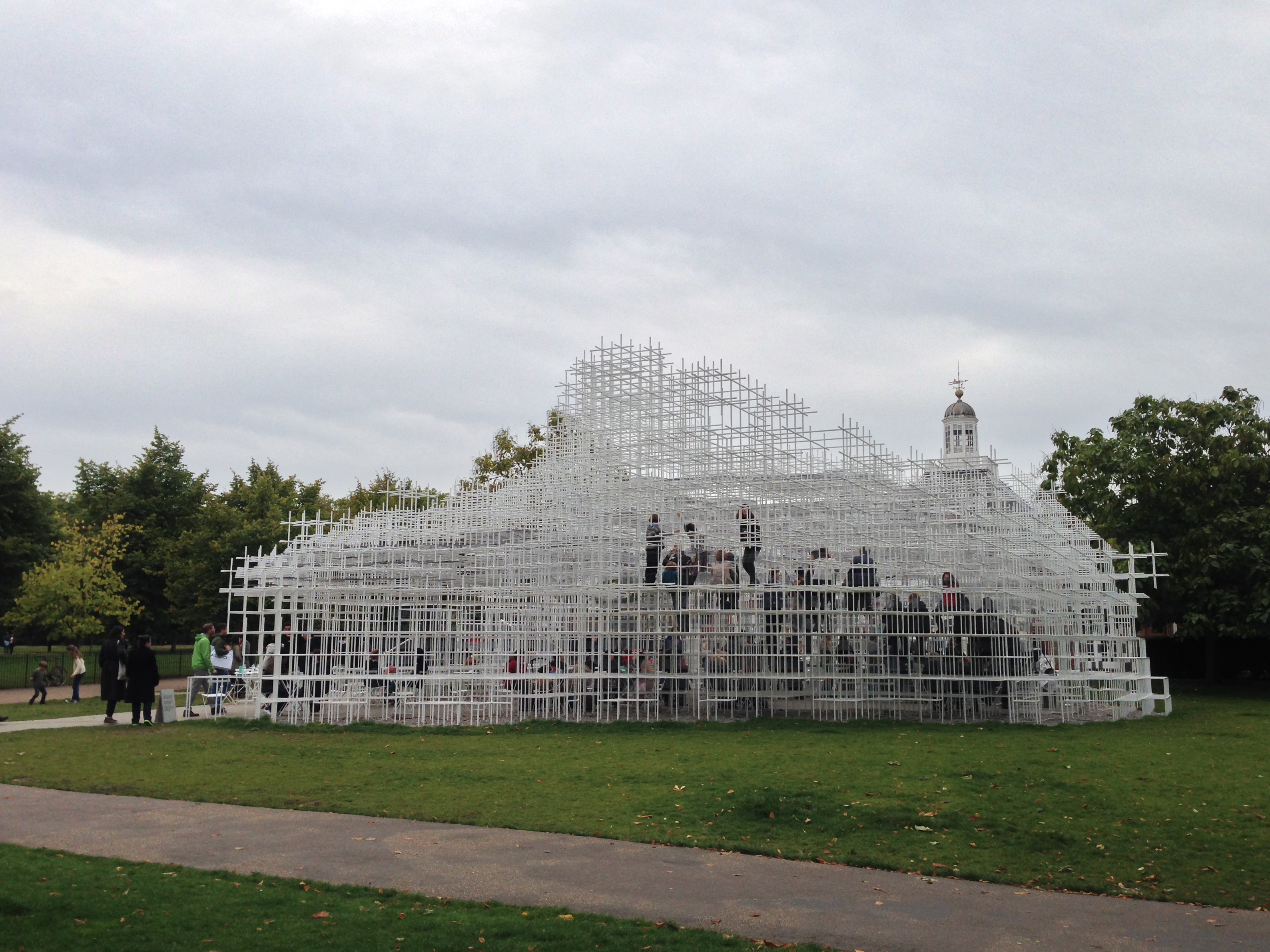
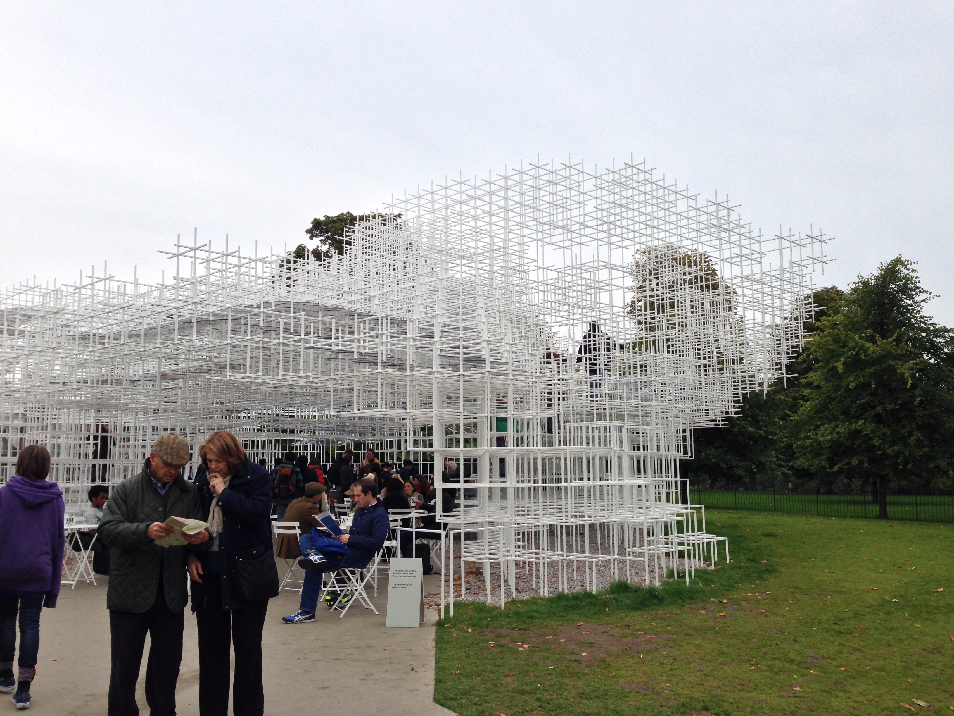
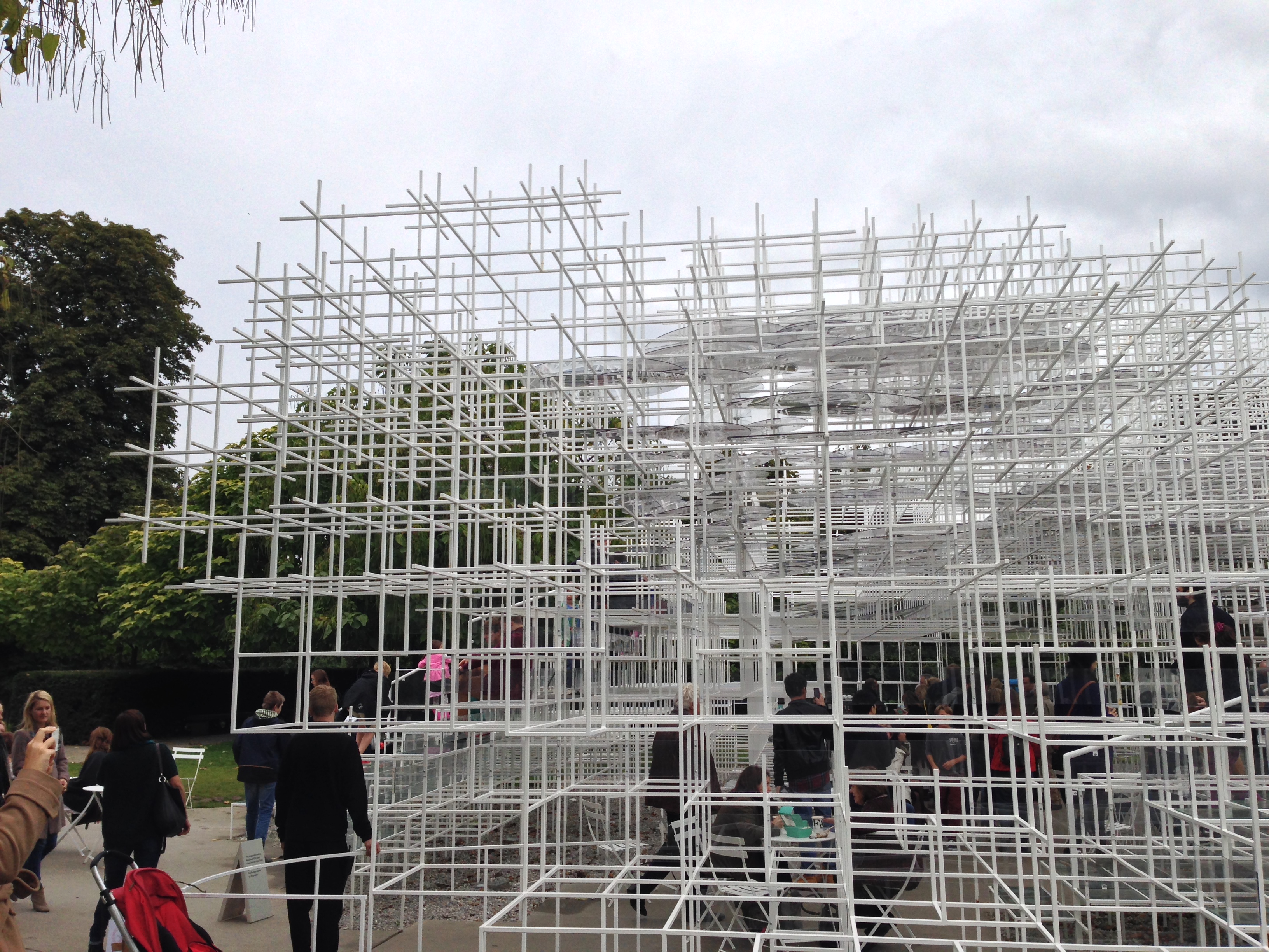
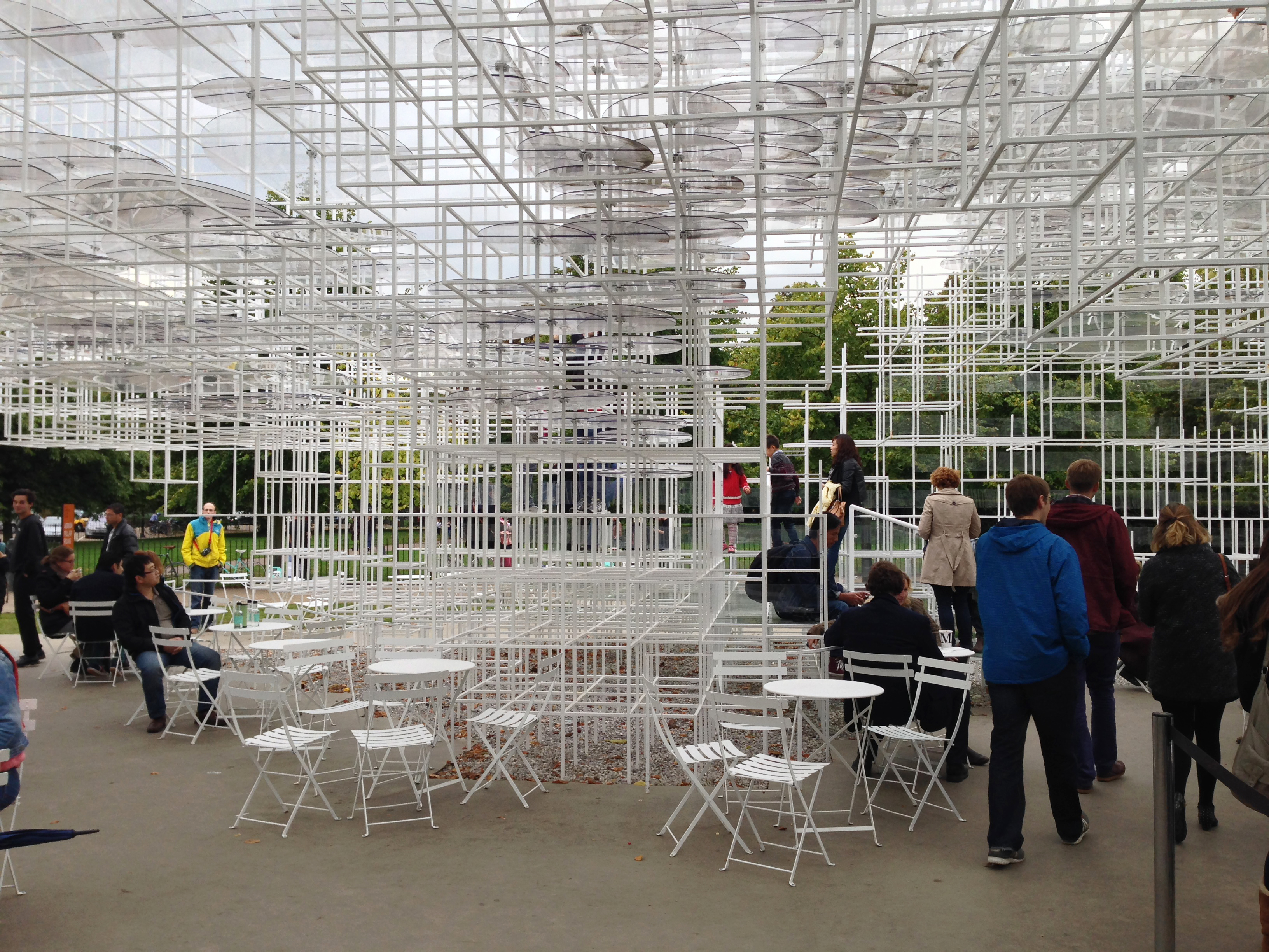
2013 Pavilion for the Serpentine Gallery was conceived as a social space free flow Fujimoto describes as “a clear field.”
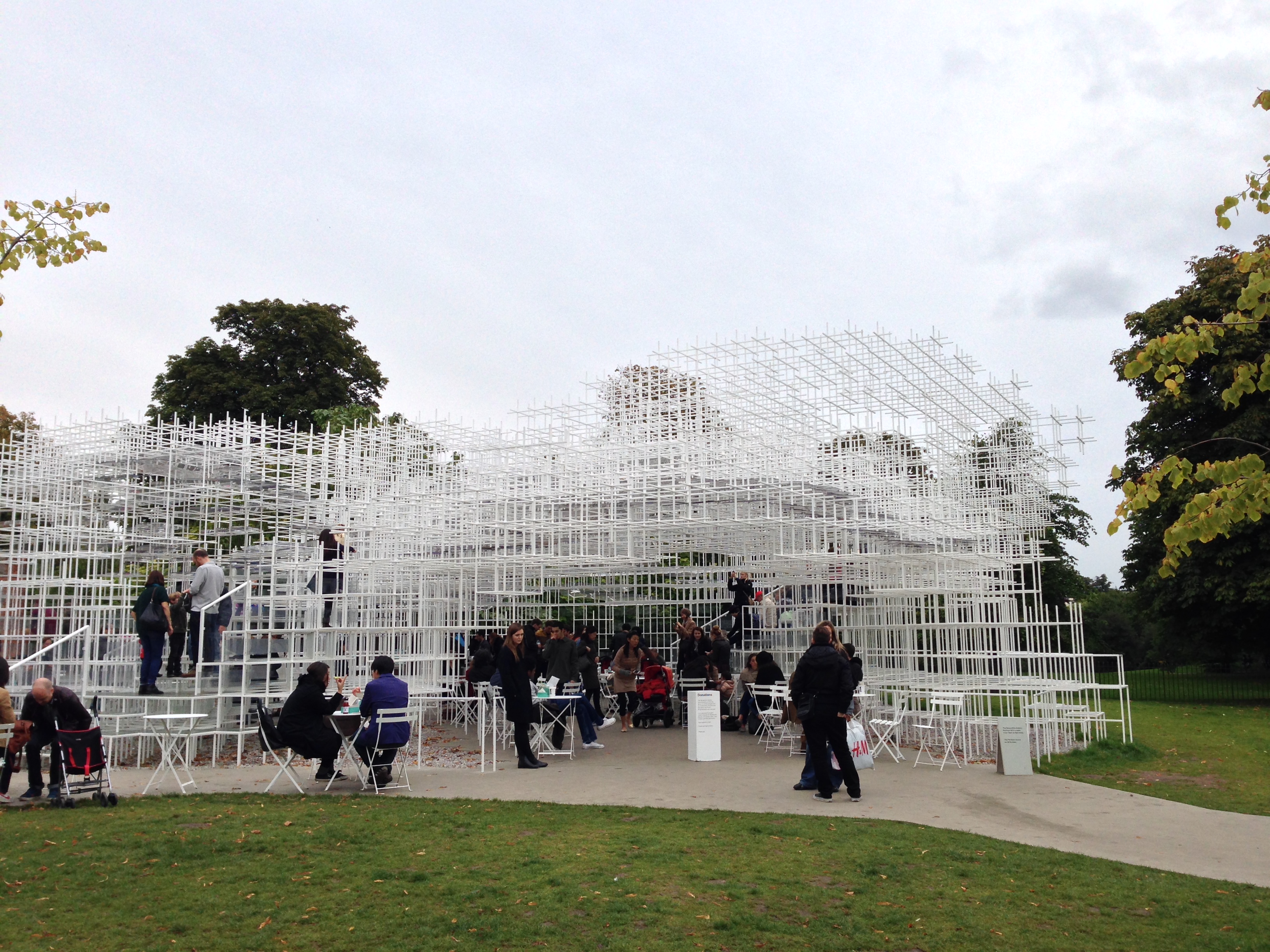
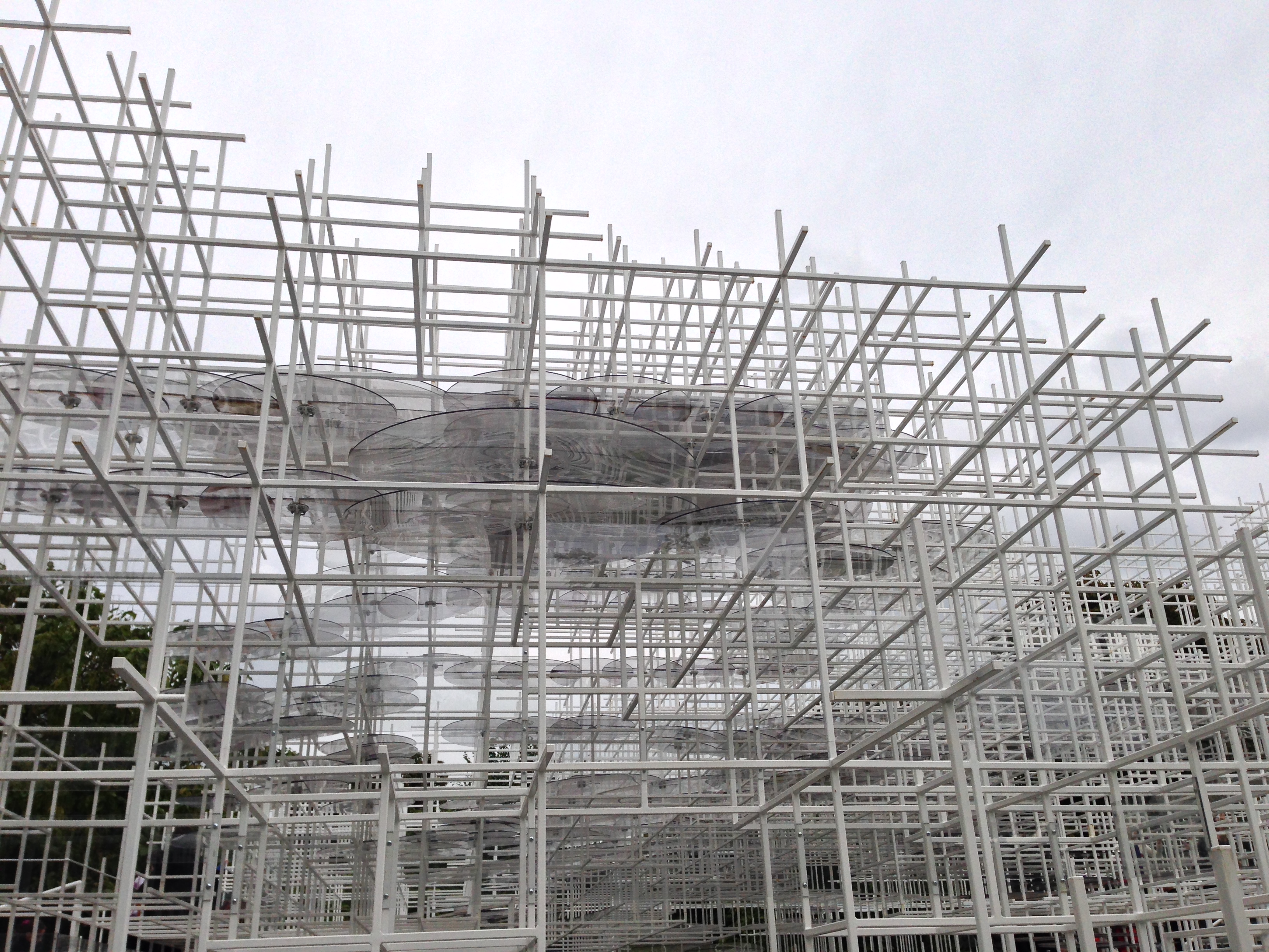
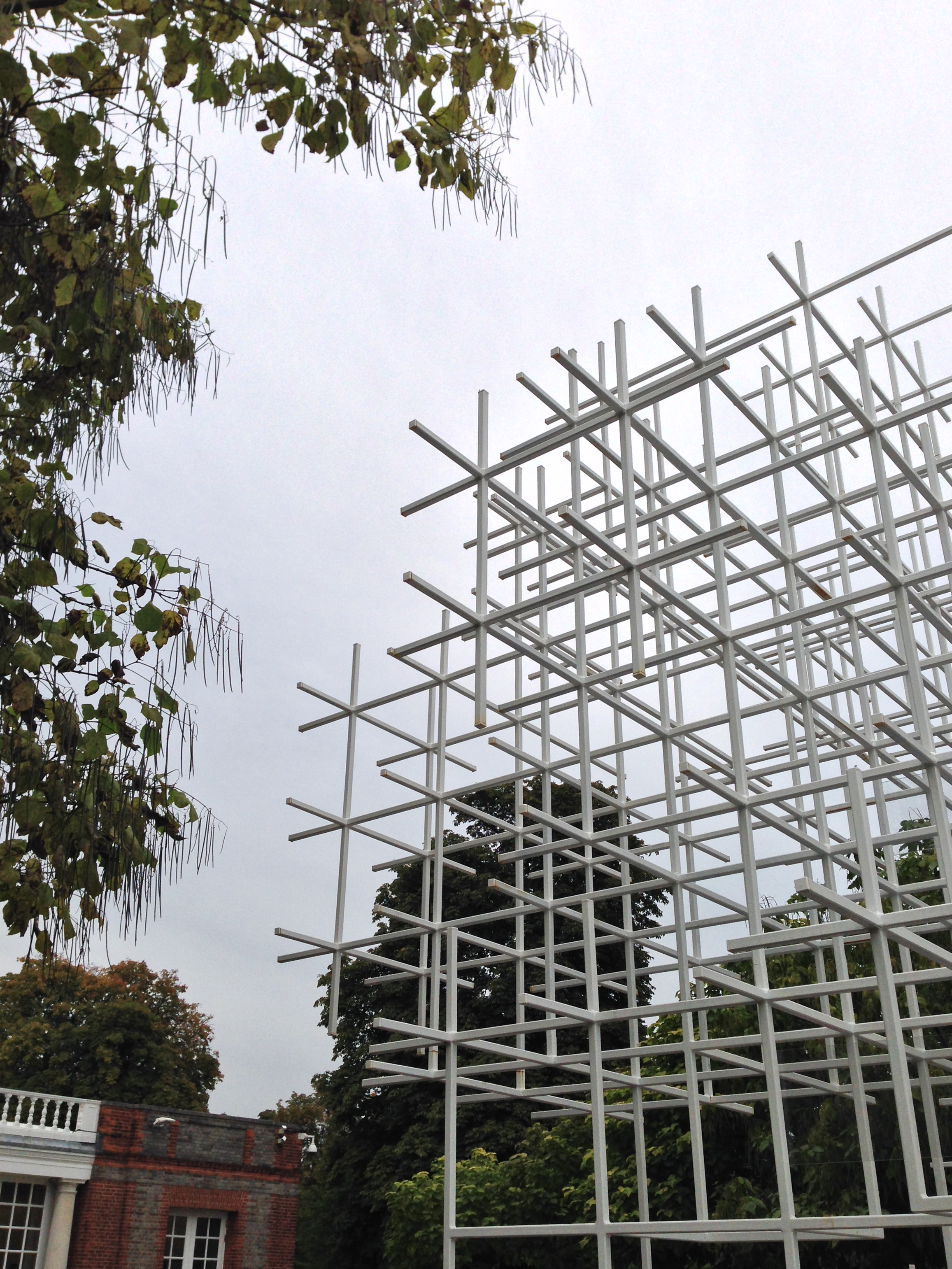
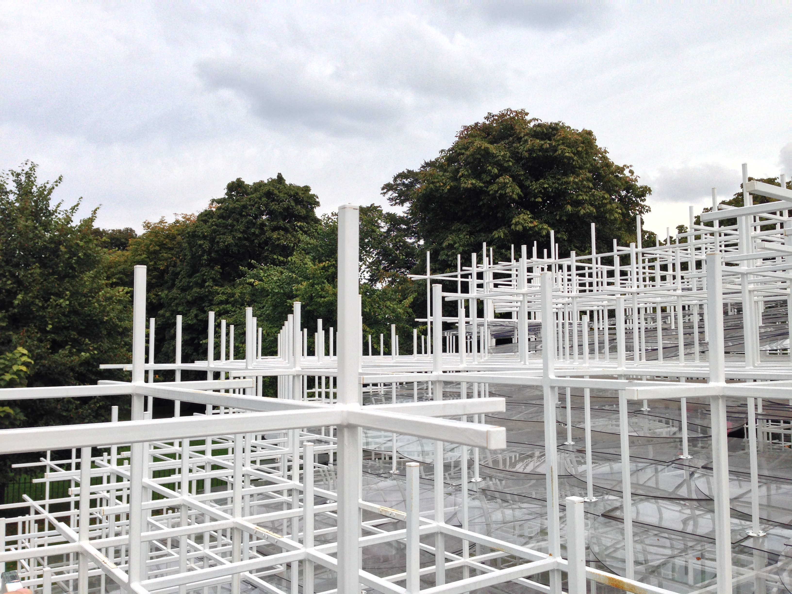
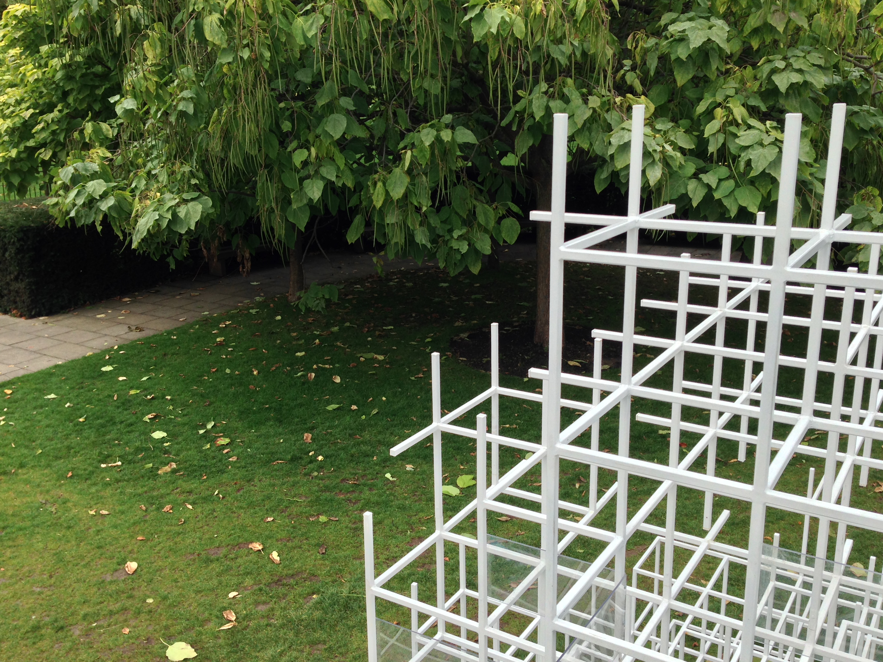
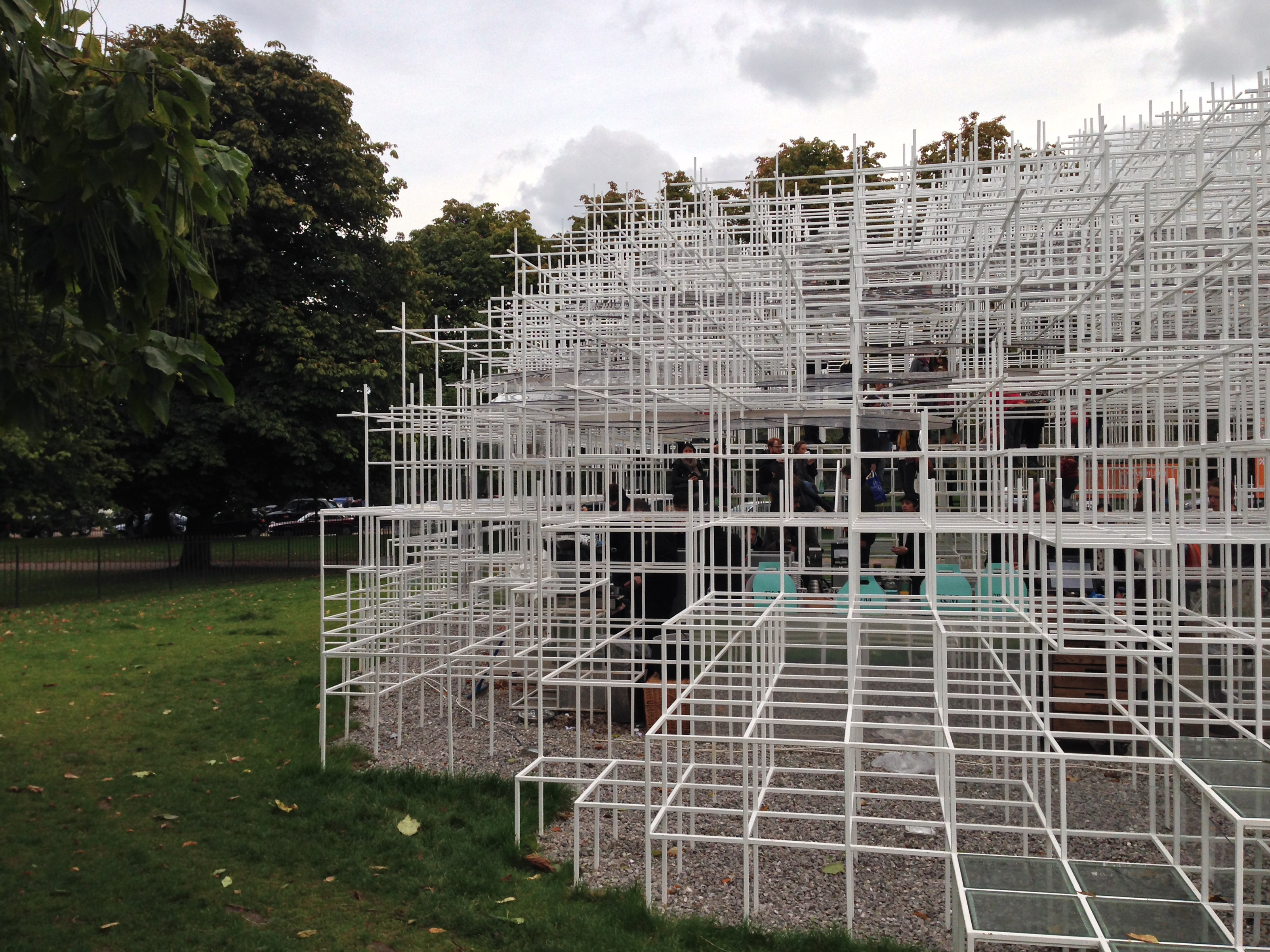
Inspired by the organizational structures, such as the forest, Fujimoto flagship buildings inhabit the space between nature and artificiality. This concept has also been applied to the design of the Pavilion 2013, whose light and semi – transparent structure allows the integration, ethereal as a cloud, with the green of the place and the bottom of columns classic East Wing Gallery.
Describing his design concept, Sou Fujimoto said :
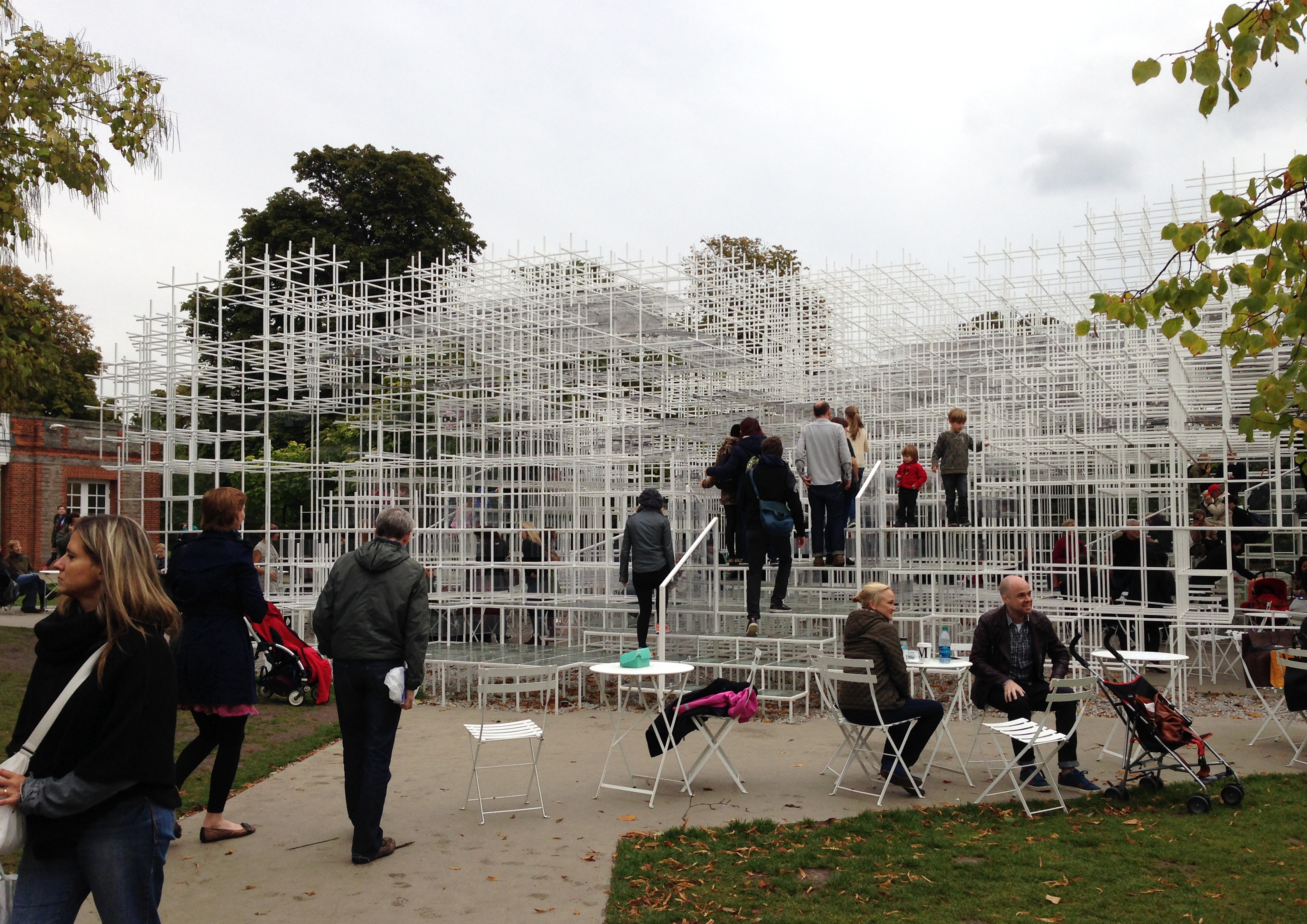
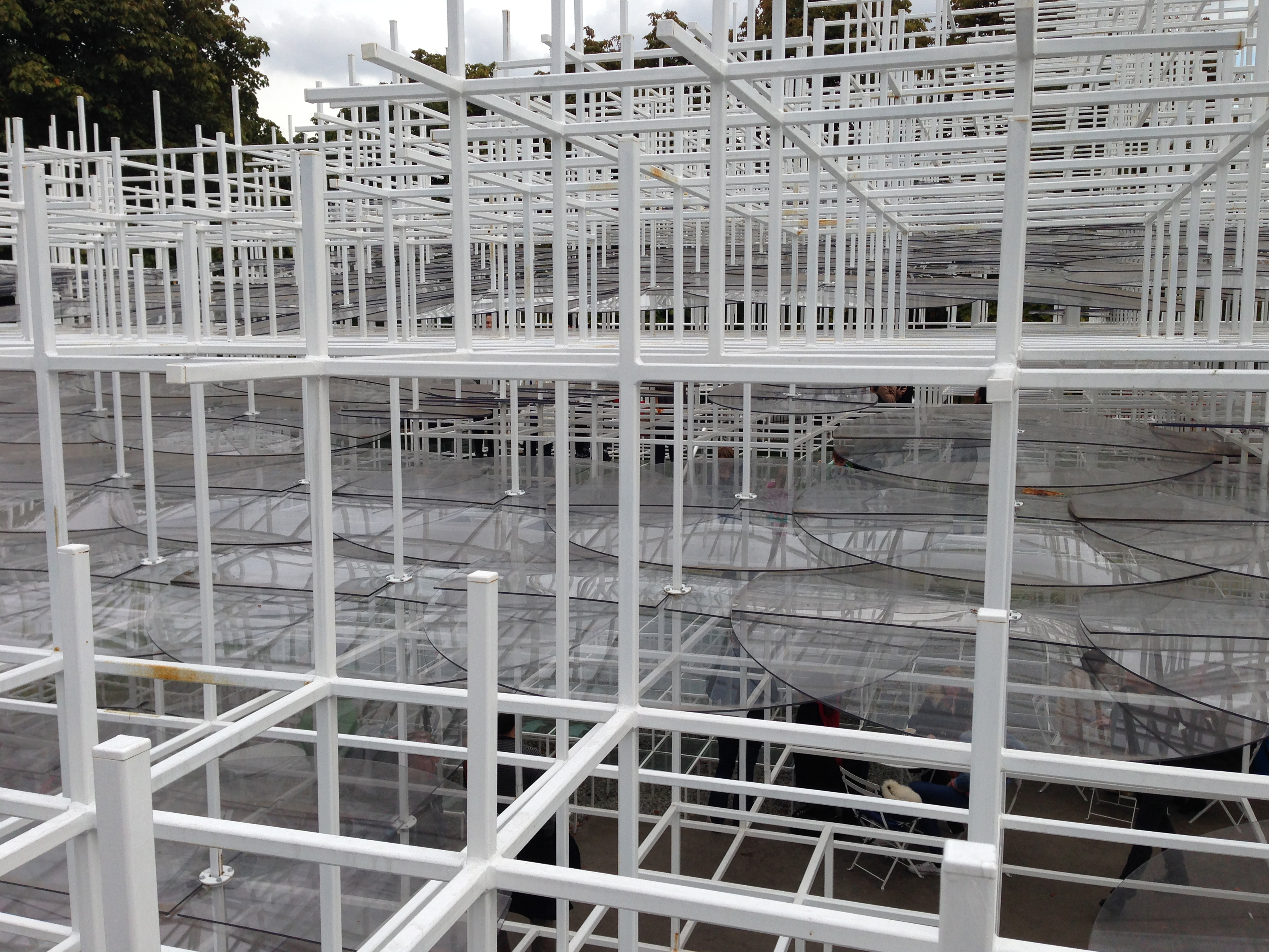
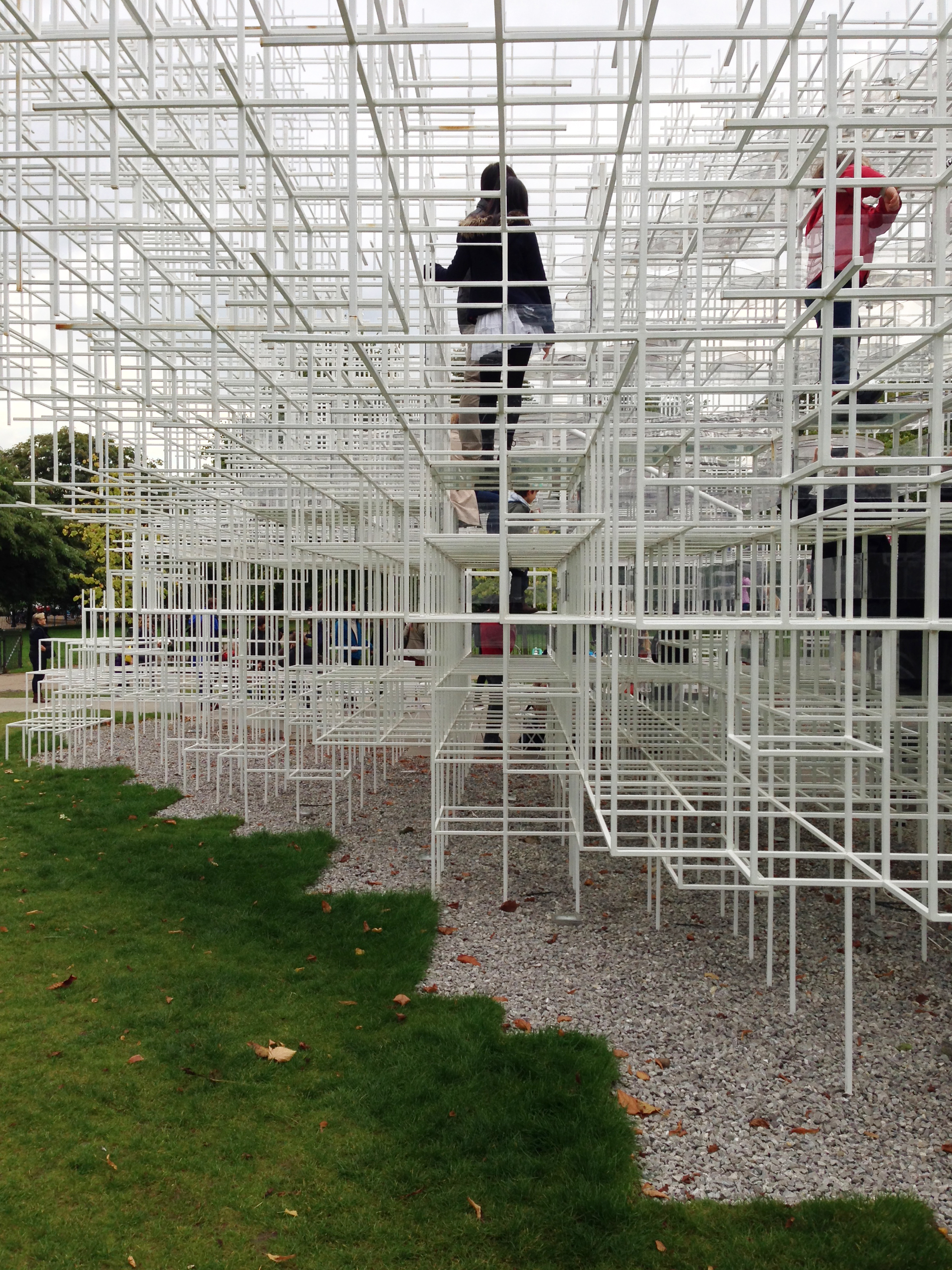
” To the Pavilion 2013 propose an architectural landscape : transparent ground encourages people to interact with the site and explore it in various ways. Landscaped Within the context of Kensington Gardens, I imagine the vivid green of the surrounding vegetation intertwined with a structure geometric. A new form of environment has been created, where the natural and the manmade arises, not only architectural or only natural, but a single meeting of the two. Pavilion is a delicate structure, three-dimensional, each unit makes up bars thin rectangular steel 800 and 400 mm. shall form a transparent and irregular, simultaneously protecting visitors from the elements and at the same time allows them to become part of the landscape. footprint of the structure is 350 square meters and the Pavilion will with two hits. A series of terraces provide seating areas that will allow the flag to be used as a flexible and multipurpose social space. ‘s delicate build quality, enhanced by its semi – transparency, create a cloud shaped geometry, like mist rising from the ripples of the park. from certain vantage points, the Pavilion seem arise from the classical structure of the Serpentine Gallery, with visitors suspended in space. ”
Description and materials
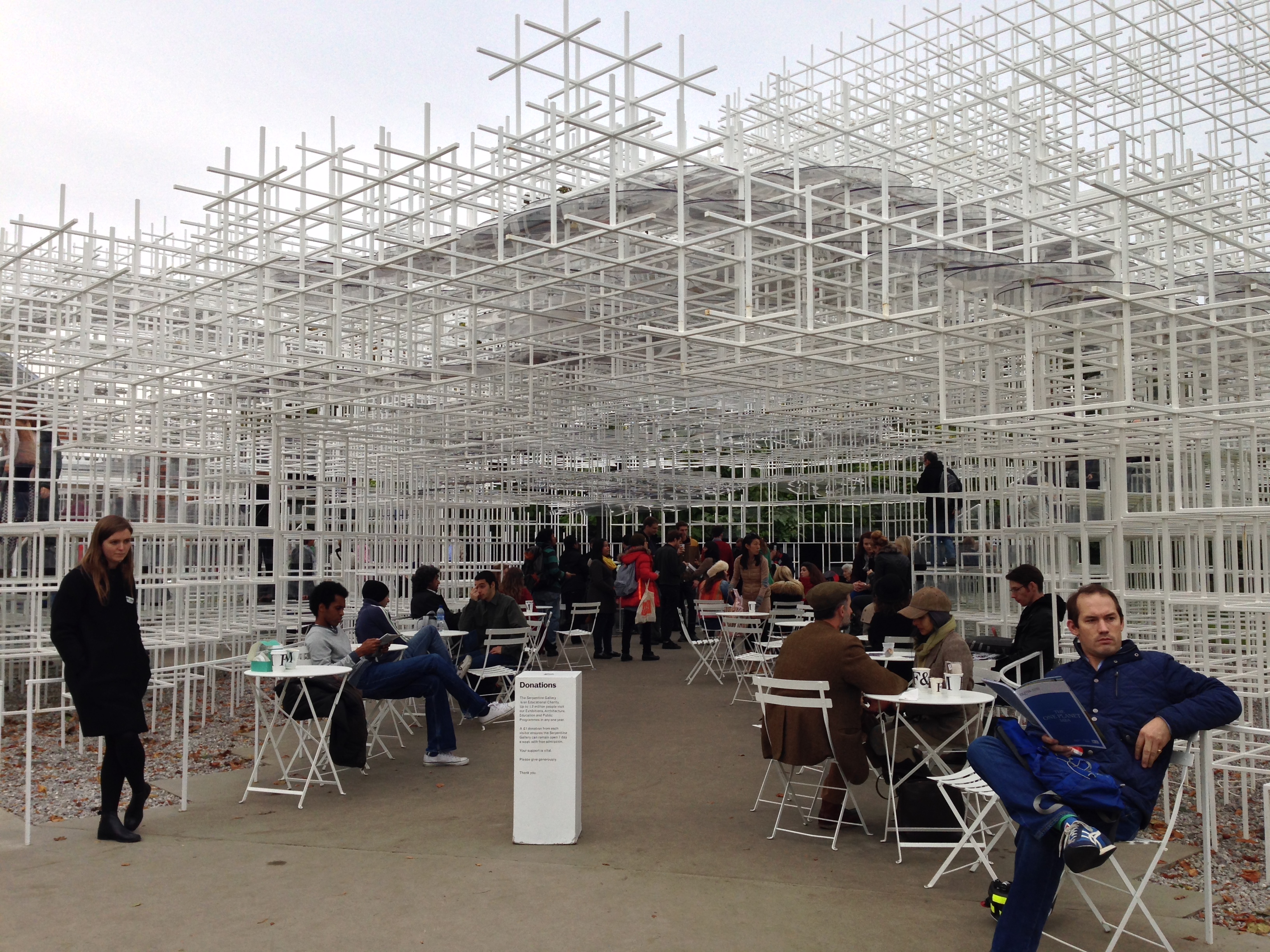
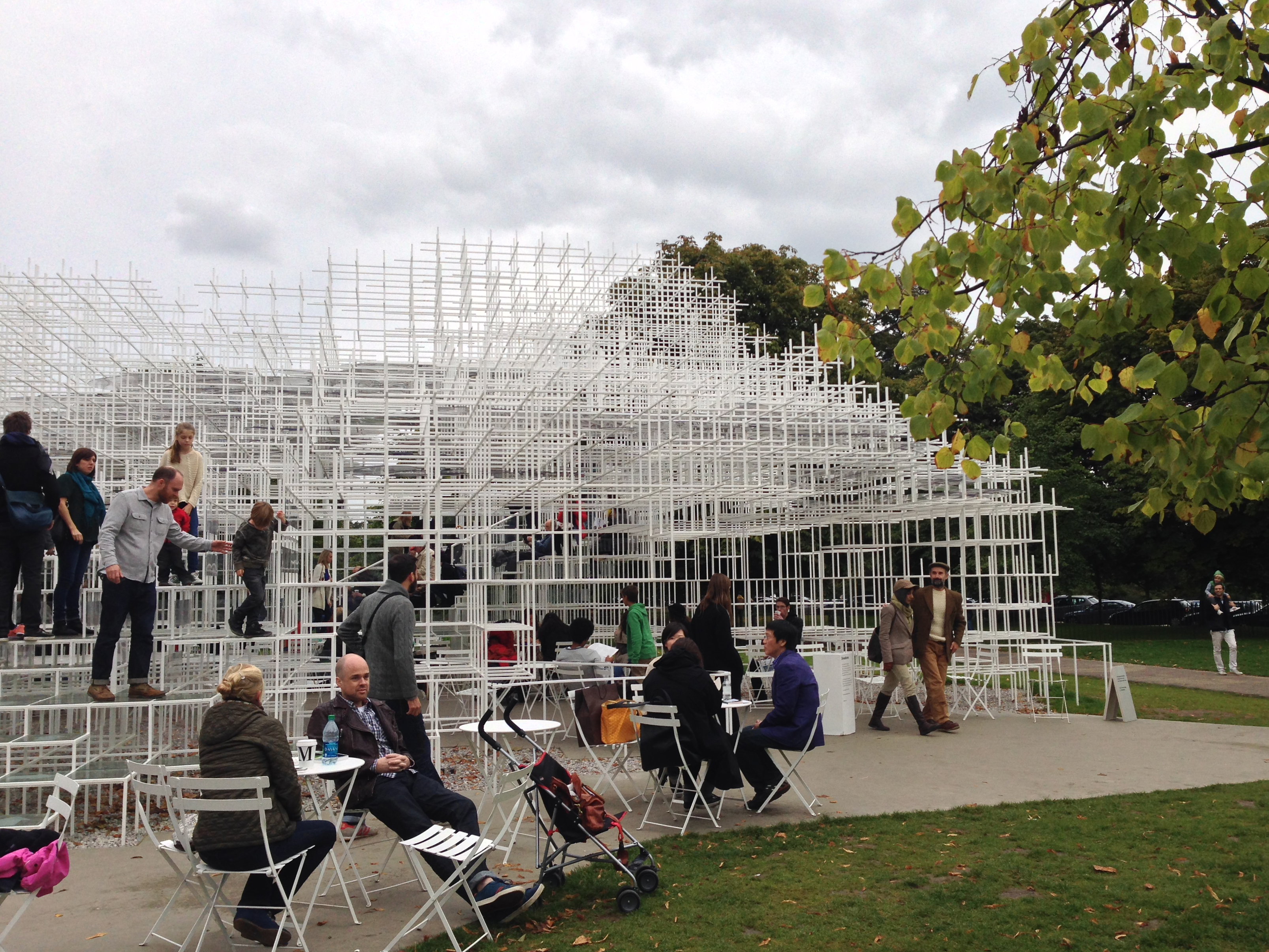
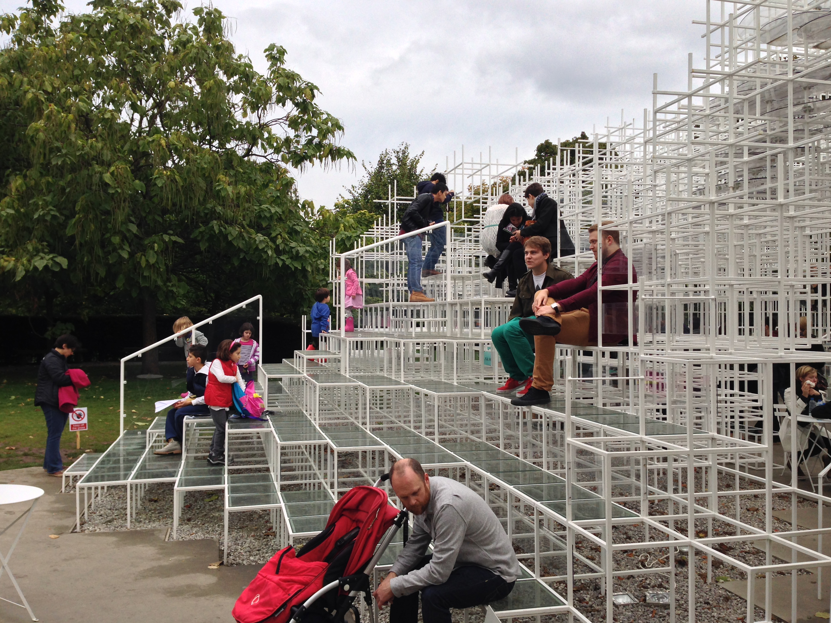
Designed as a flexible and versatile, its global footprint occupies 350m2 offering the possibility of the public who visit inside can interact in different ways. It has two inputs and for the first time in the history of the Serpentine Gallery Pavilions, works inside a coffee.
Gallery directors commented, “…. The harmonious combination of architecture, technology and nature do the work of Sou Fujimoto perfect milestone for the Serpentine Gallery, to Kensington Gardens and the city of London this summer 2013. We are thrilled with the result… ”
• Polycarbonate
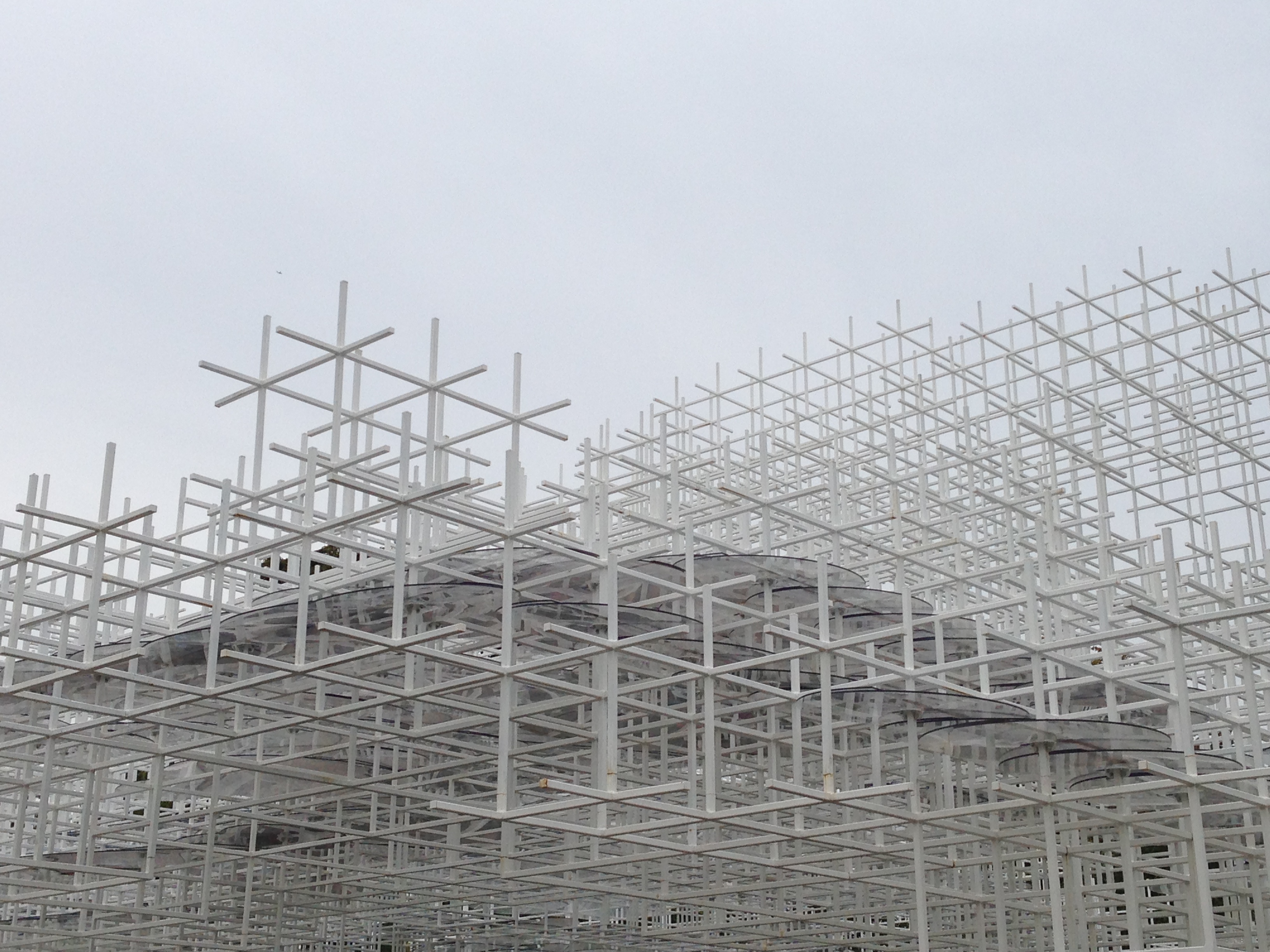
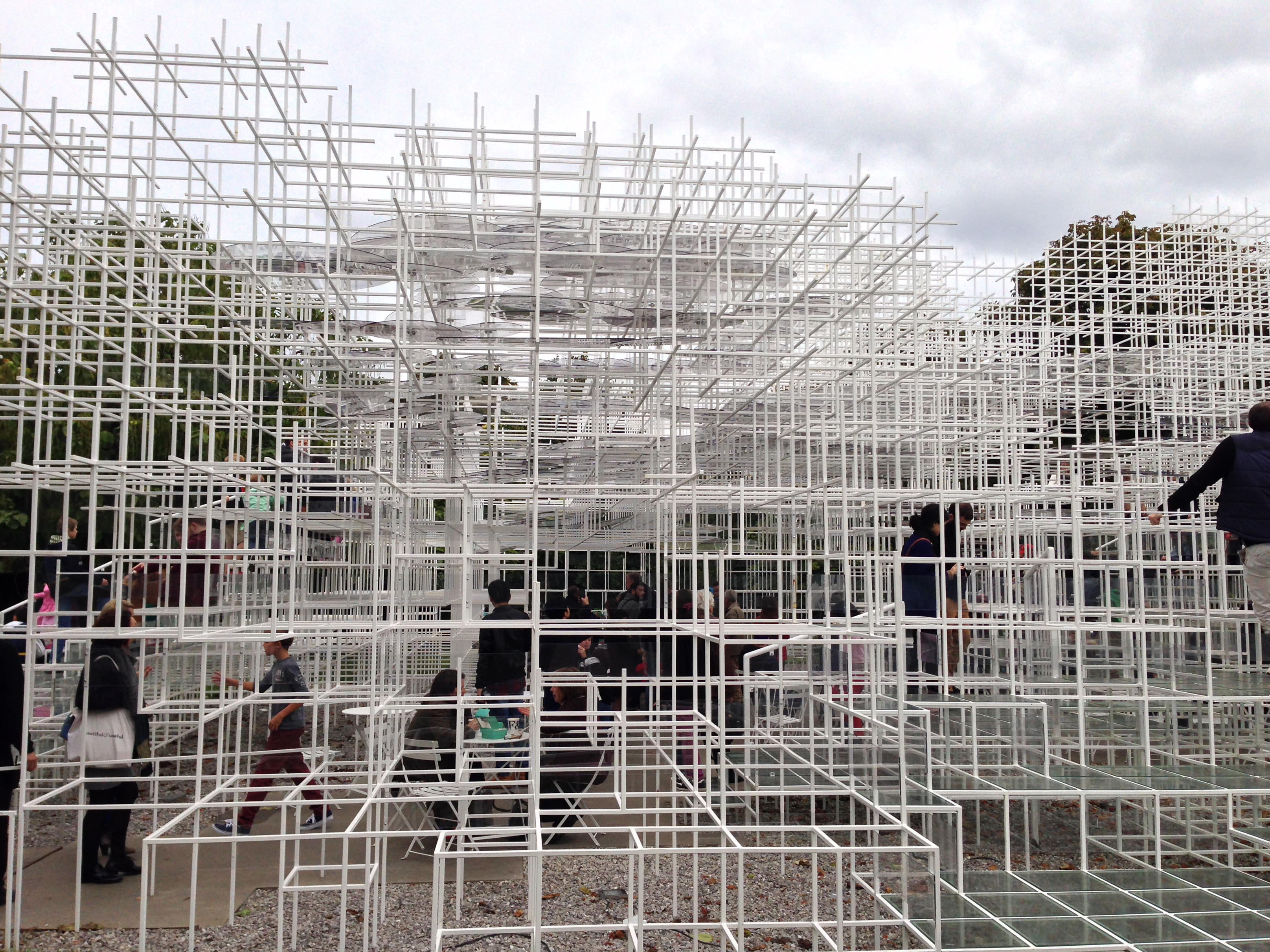
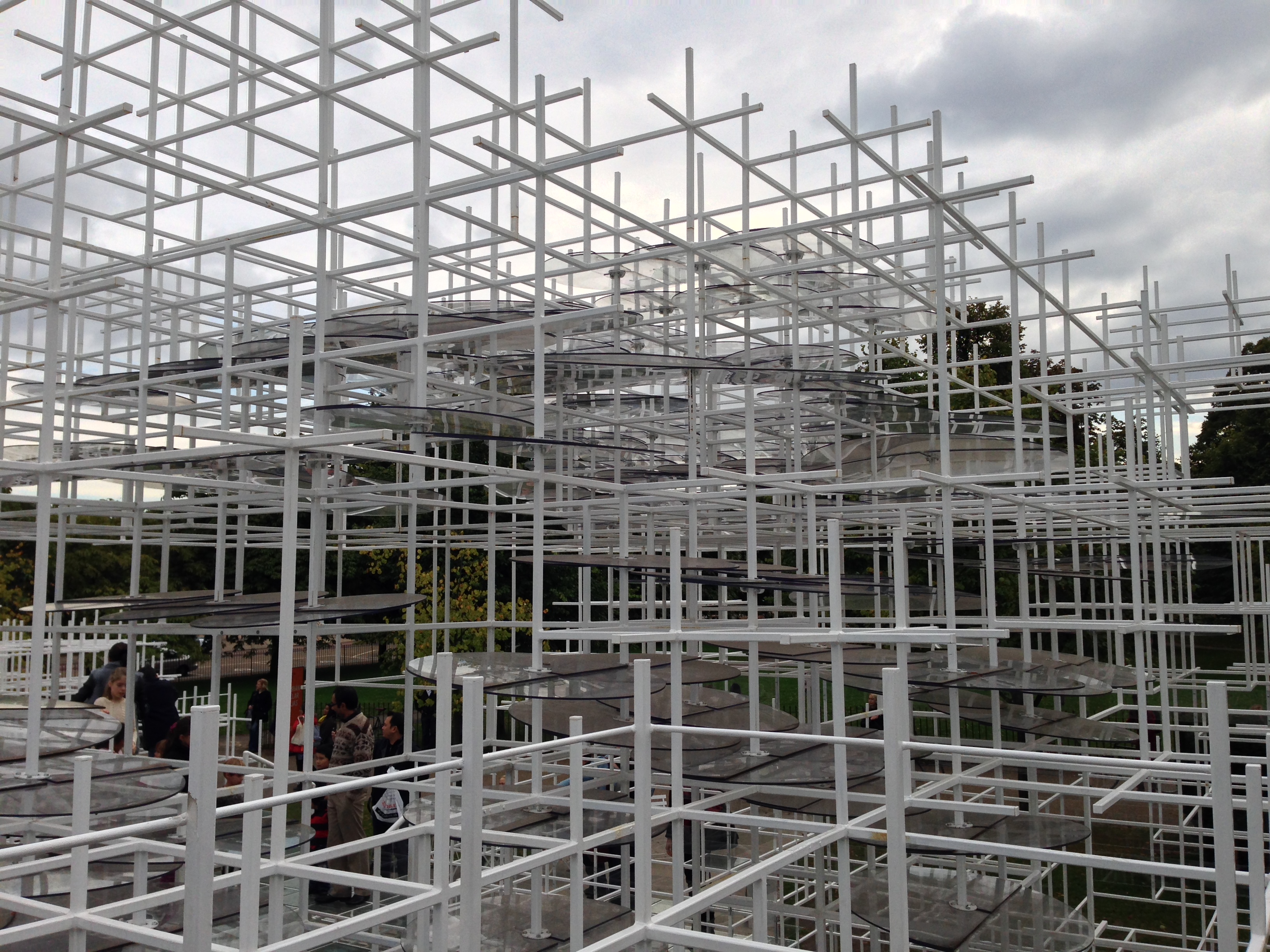
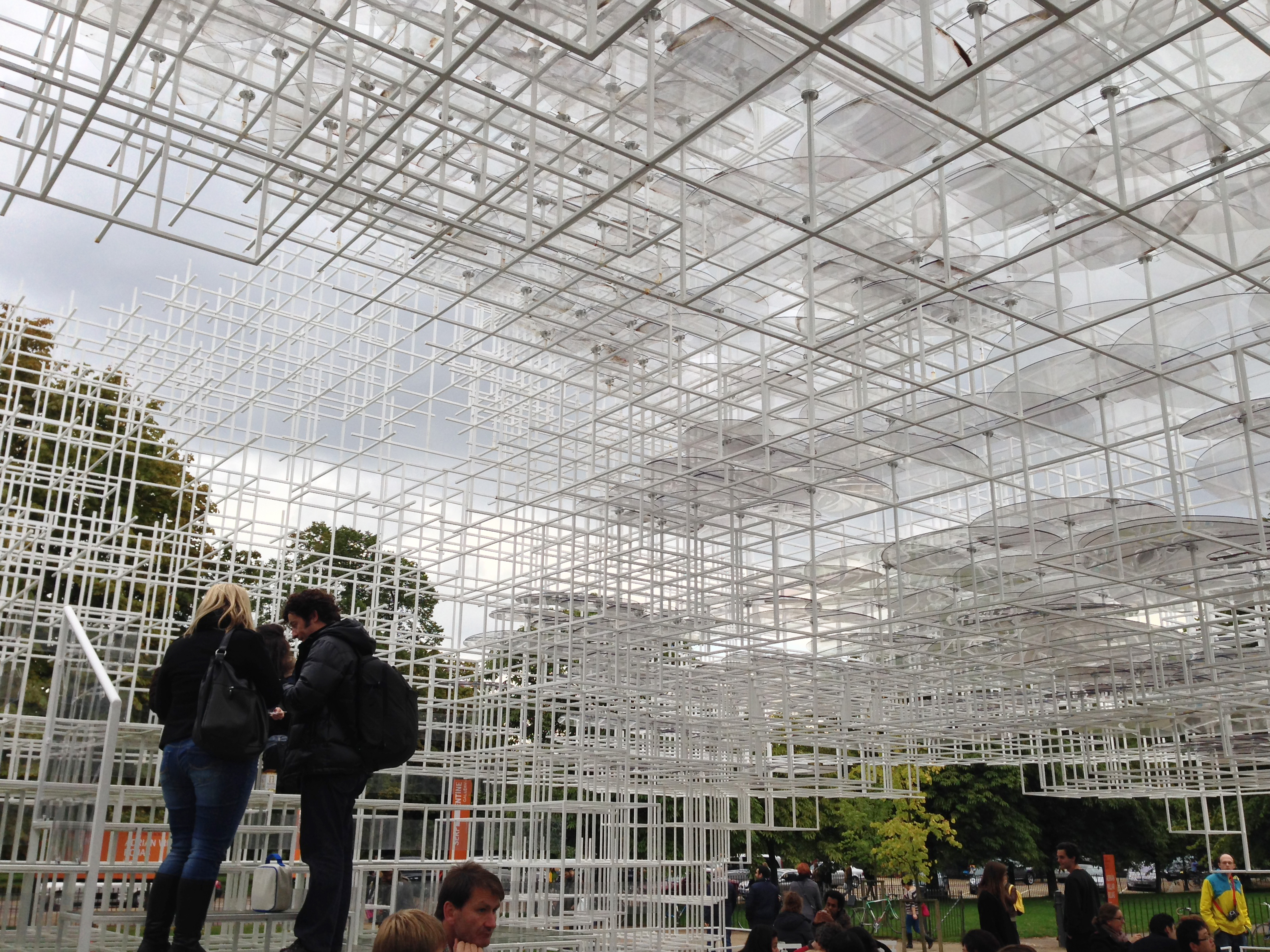
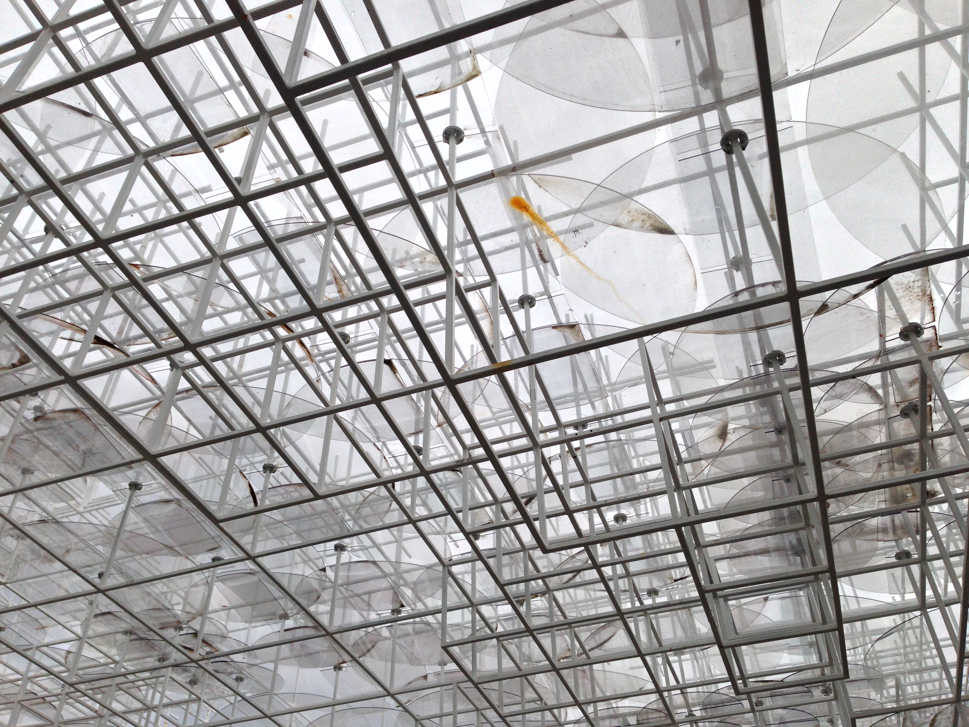
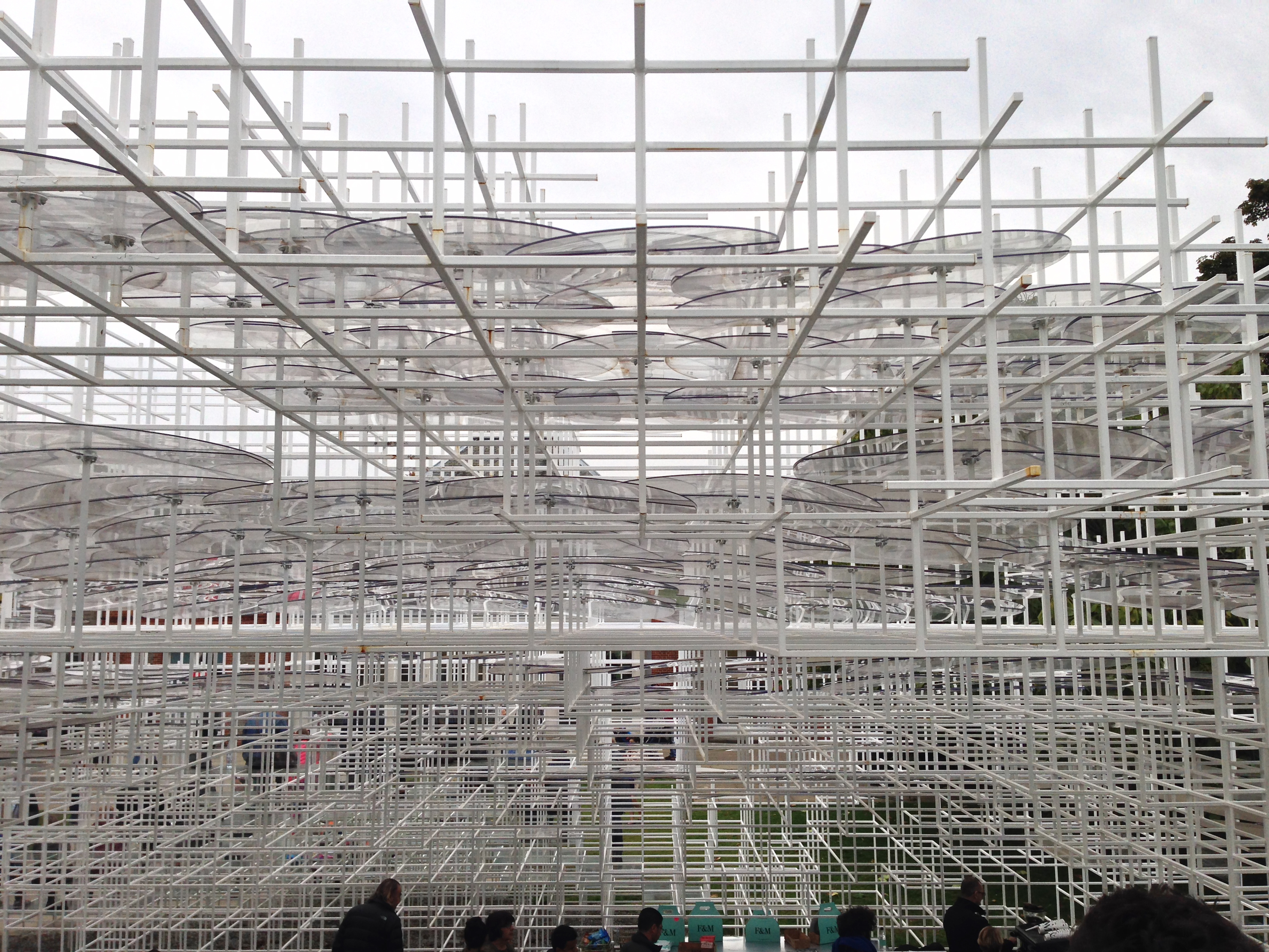
Polycarbonate circles between the poles provide shelter from the rain, but also create a layer that reflects sunlight from the inside.
The abstract network areas designated to serve a specific function are equipped with transparent elements hardly noticeable. Polycarbonate discs in clusters in the roof serve as protection against the rain. The installation tries to replicate the open structure of the clouds, which works by varying the density of intake modules sunlight through black steel construction. When the sky is clear, polycarbonate discs accentuate the look of the gray clouds, with its curved contours.
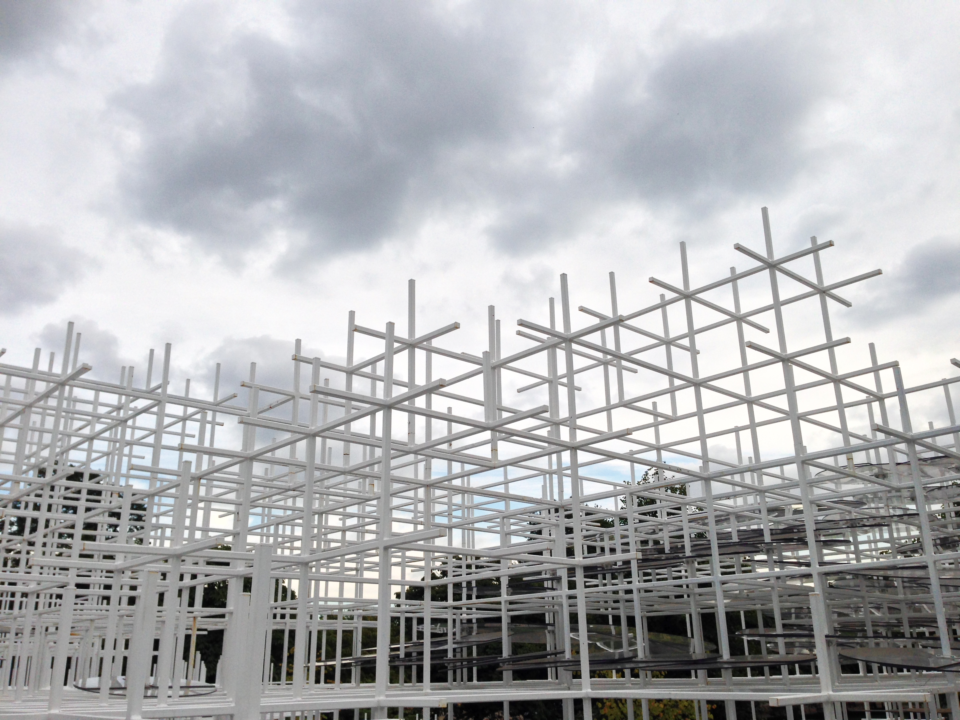
The delicate quality of the structure, enhanced by its semi – transparency, creates a geometric shape like a cloud, like mist rising out of the undulations of the park. From certain points of view, the Pavilion seems to merge with the classic structure of the Serpentine Gallery, with visitors suspended in space.
• Safety measures
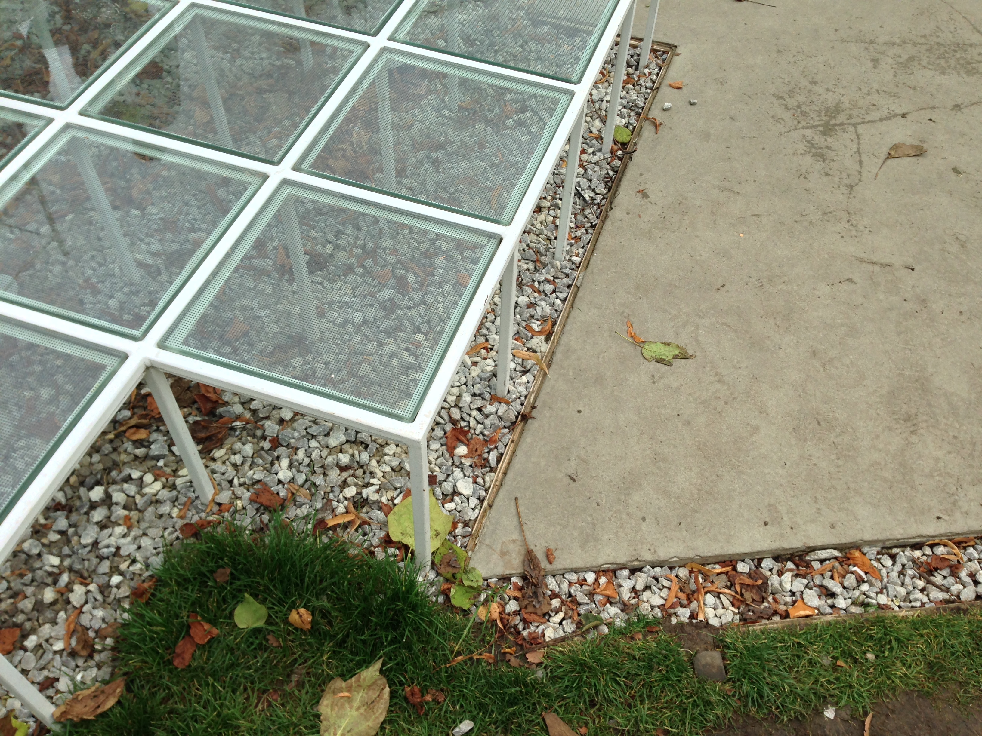
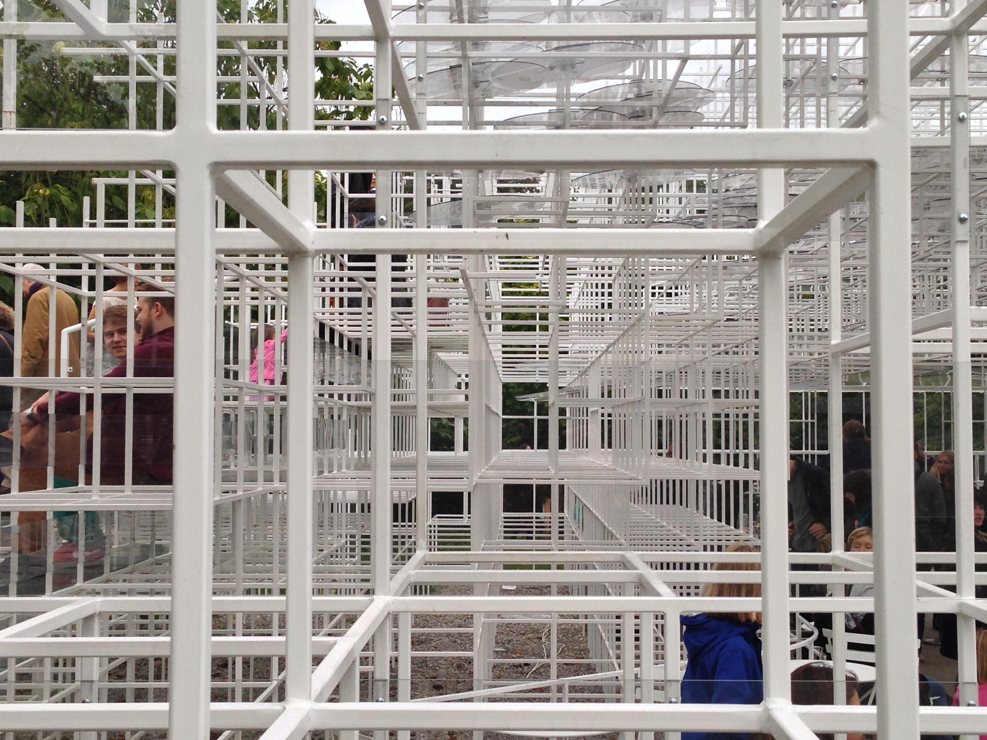
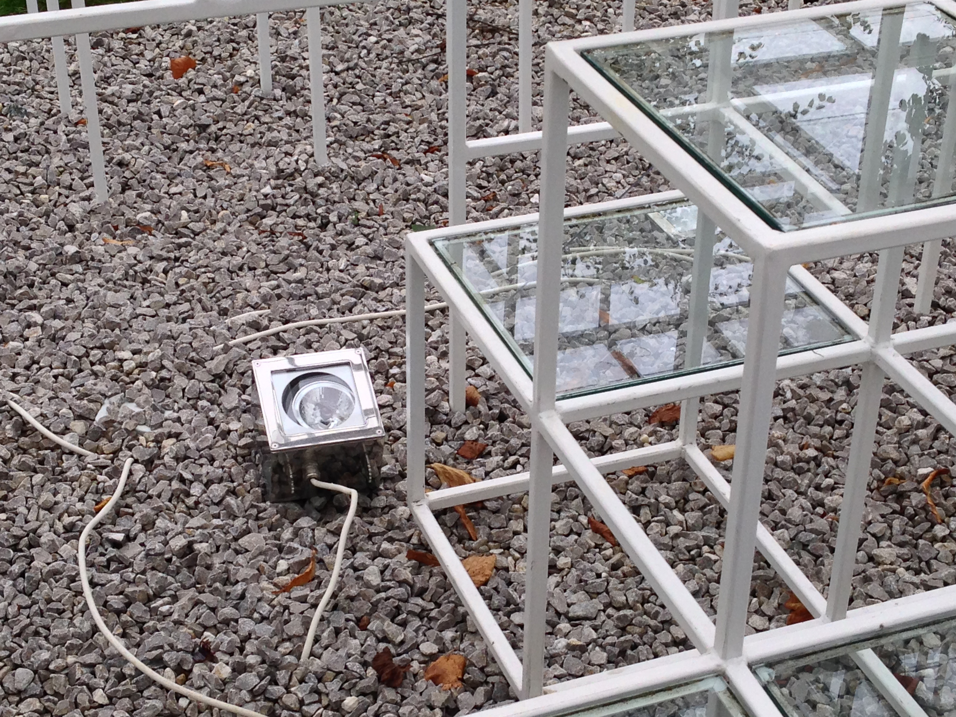
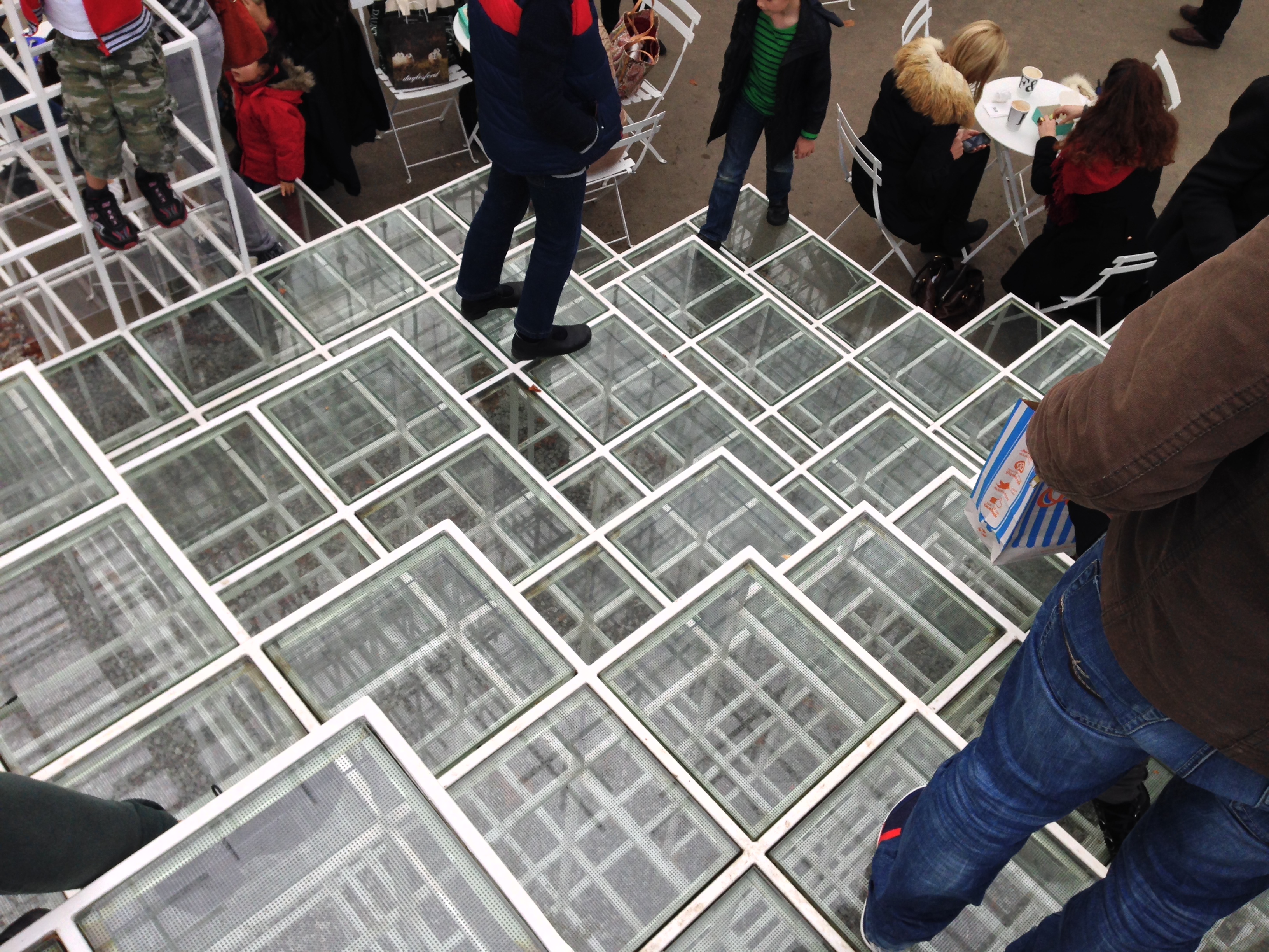
Printed slip glass panels fill the gaps of the structures close to the ground, offering more comfortable seats than you might expect. Polycarbonate strips fill the spaces between seats to prevent children from falling through the three-dimensional grid, like thin rods to prevent the fall are positioned unobtrusively.
Binding component
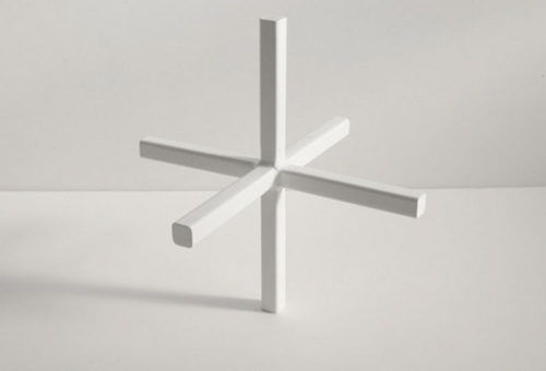
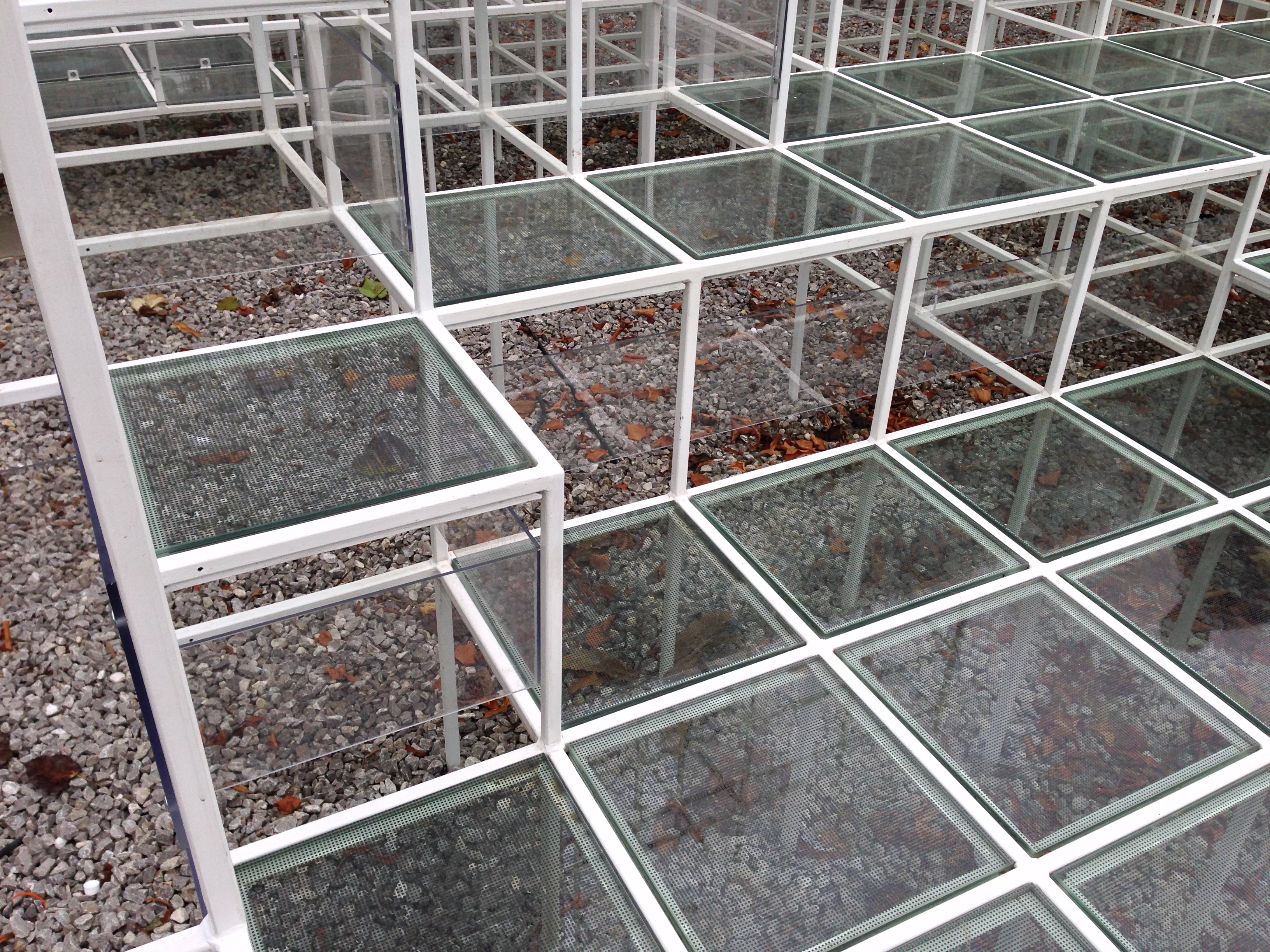
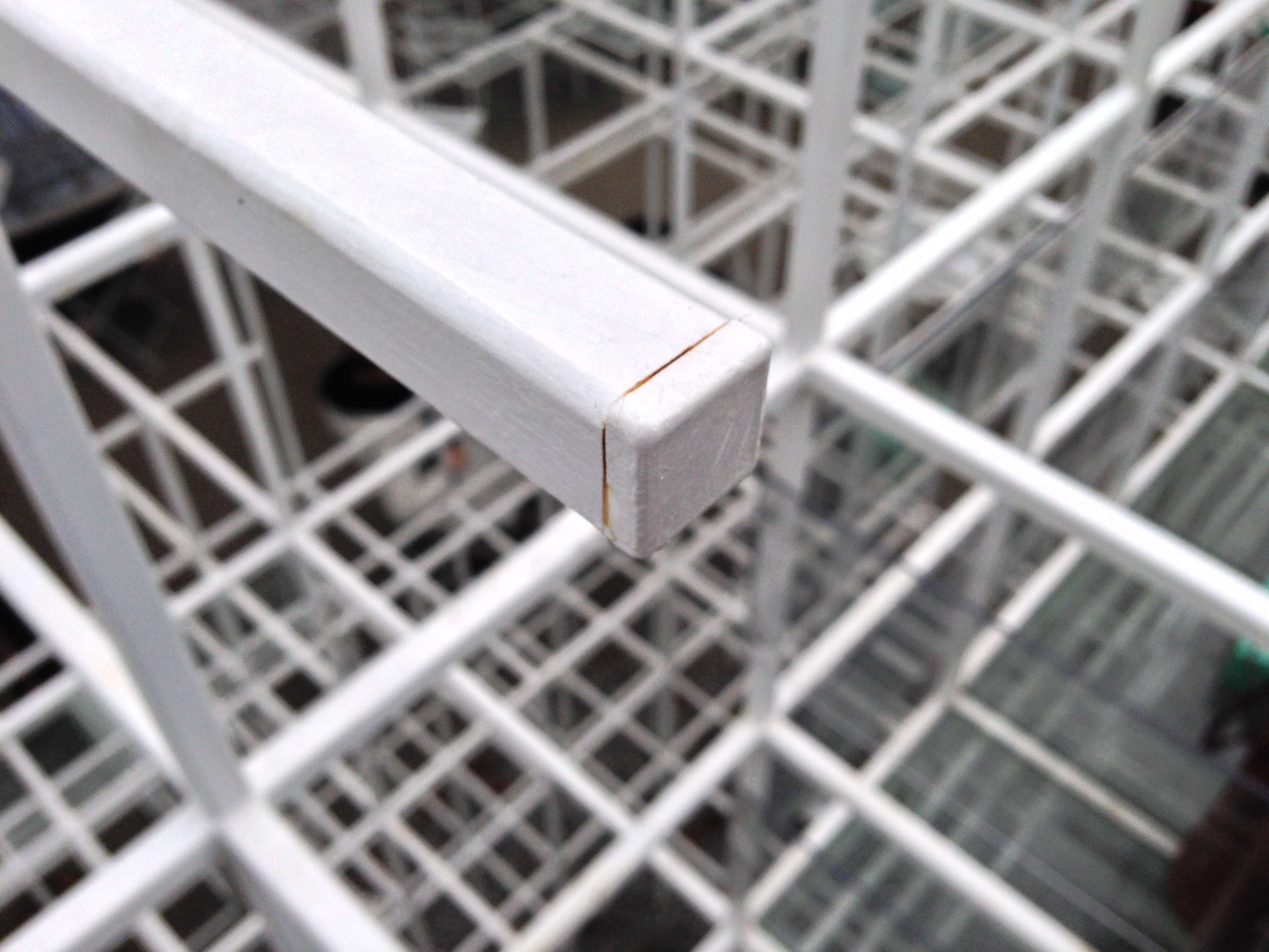
For this particular design, Fujimoto has created a series of steel modules attached, 30 x 30 x 30 cm, derived from their original architecture, these same modules form the superstructure of the Pavilion. These components are not only the structure of the pavilion, but also hold it together. The shapes of the joints and connections are key in all the work of the architect, defining use of aesthetics as well as the spirit of their practice.
• LEDs
Headquartered in London, United Visual Artists (UVA ) have given life to Sou Fujimoto structure with an “electrical storm ” of LEDs. In order to make the architecture ” breathe” from within, UVA has a network of perfectly integrated LED lights inside the lattice, which mimics natural forms of a thunderstorm. In addition, carefully conducted auditory effects further enhance the experience, the transformation of ” flag radical” in a cloud geometric Fujimoto electrified.
Engineering
The new Serpentine pavilion has more than 26,000 steel brackets, each working hard to give shape and strength to the structure. The level of detail almost caused a collapse in the computer systems of AECOM, the engineering firm that helped in the realization of the design, in fact a system upgrade needed to manage information and meet the challenges of lighting and fire protection the complicated structure Fujimoto.
Perspectives
Orthogonal
The variation in floor covering corresponds to the transition from the inside to the outside. The floor sections coated with glass panels echo polycarbonate discs on the ceiling. Seen in an orthogonal direction, the structure has a clear and delicate appearance.
Transitions are worn skyward as the edges of a three-dimensional carpet or the branches of a tree.
Diagonal
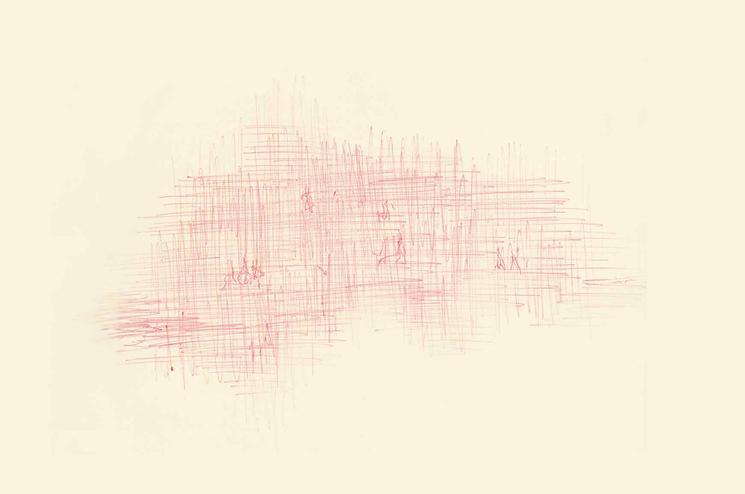
From a diagonal, the sections begin to oscillate with beams of light entering through the network, a constructivist – futuristic stage set comes with the changing sunlight through the clouds. Friedrich Kiesler Remember to ” City in Space ” at the Exhibition of Decorative Arts in Paris in 1925.
Structure
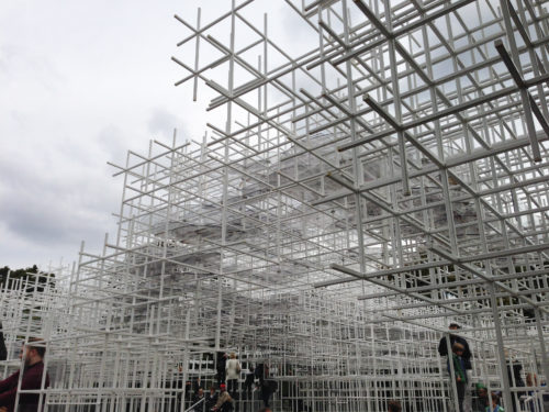
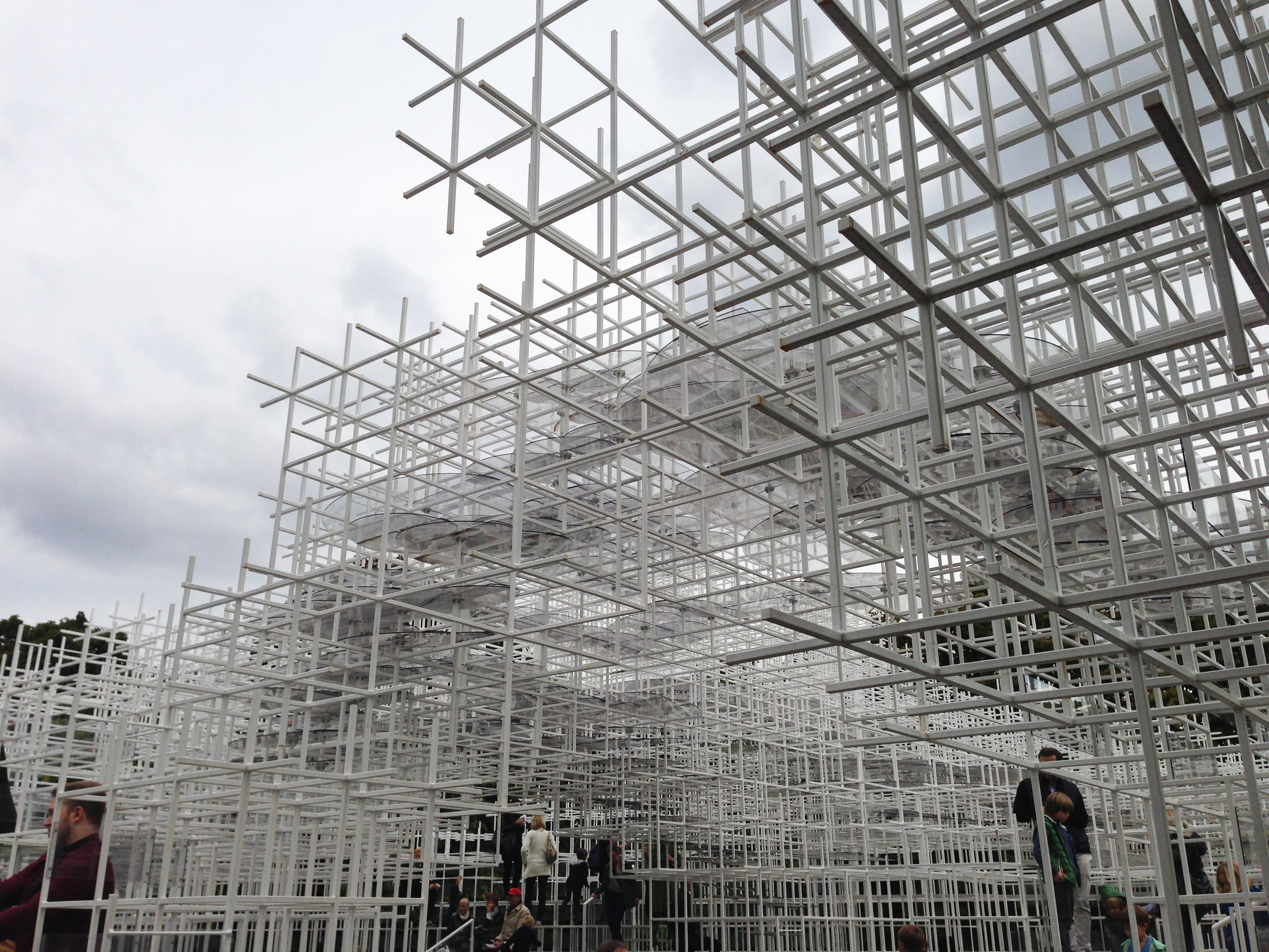
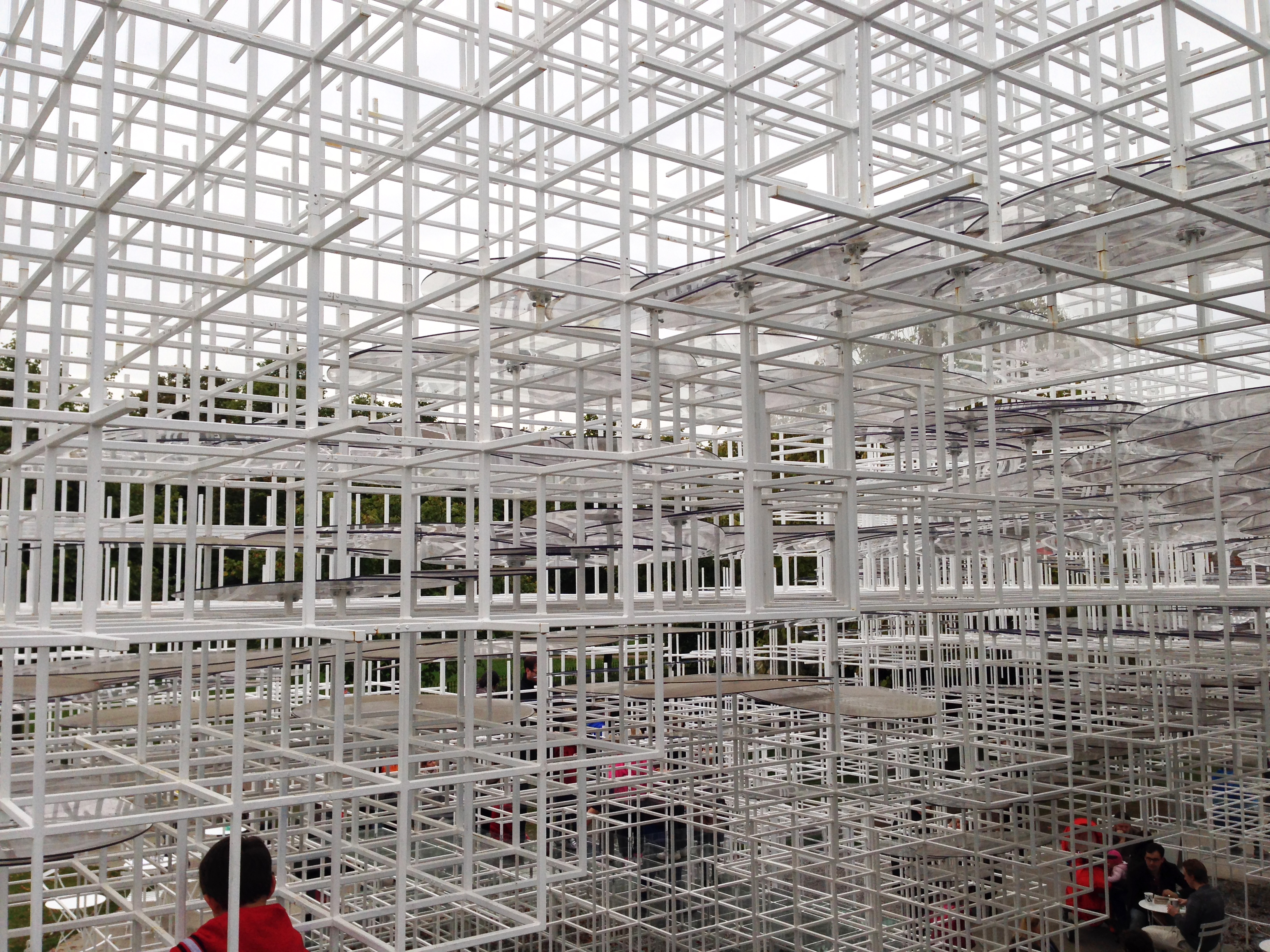
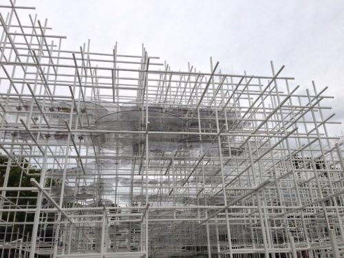
The unique and delicate three-dimensional structure is formed with thin steel bars 20mm white together in a complex lattice pattern that seems to rise from the ground as a brilliant array.
350 square meters have been created with a 3D lattice structure comprises a series of interlocking cubes with sides 40 or 80cm tubular posts made from lightweight steel 20mm, more than 26,000. The simplicity of the means that creates the most complex Fujimoto spatial effects through aggregation and disaggregation is absolutely riveting. Steel studs of two square centimeters in width forming the three dimensional coordinate system which is the starting point geometry and construction of the welded structure.
On the structure will support semi- transparent rings and irregular that protect visitors from the elements while allowing them to remain part of the landscape. These terraces offer rest areas that allow the pavilion to be used as flexible social space.
Loads
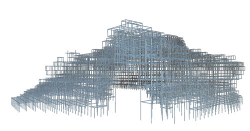
The complexity of the structure made it essential to have a three-dimensional analysis model, since the structure is based on nearly 27,000 items for global stability. In areas where visitors are allowed access to the structure, a structure placed locally heavy duty, which is able to withstand the weight of the glass panels and the weight of a crowd gathered in the structure. This fact combined with accidental loads representing unwanted access to the roof, removing some elements and foundation settlement.
• Testing
From the outset it was clear that the detail was vital nodes had to be easy to manufacture, allowing easy construction of larger modules on the site, providing the facilities, connections and have the ability to transfer the total capacity of the section through the joint. Were developed several concepts and designs together with the manufacturer, allowing the development of different details, allowing the structure to be built within the time available.
It was necessary to ensure that the seals could mobilize the full capacity of the steel section, as it was essential for the stability of the structure, which was based on Vierendeel action frames and corresponding higher moments joints. To ensure that the joint capacity was insufficient, various test pieces were created and tested to destruction. This included individual nodes small scale and large scale models also sections of the structure.
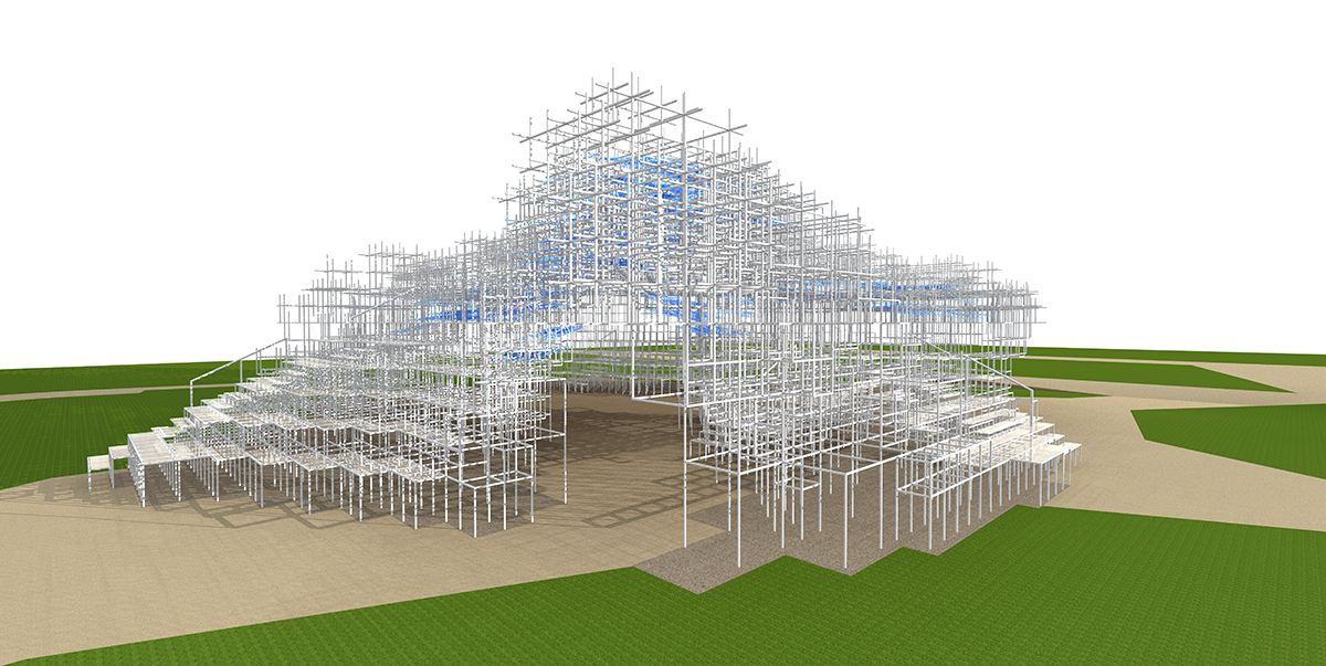
• Parametric Design Process
The program’s success was based on electronic collaboration among members of the design team. From the beginning of the project, the design concept was transmitted through 3D models, since the complex structure makes little sense when expressed as two dimensional sections. The architectural scheme has been developed using Rhino -made scripts and used to transfer the geometry of Scia Engineer. Critical to the success was the ability to make this a complete process of back and forth, allowing rapid development of the design with the architect and driving toward the end of the final solution that embodies the dream of professional as well as the structural performance.
The 3D model was also shared with the manufacturer allowing integration with the processes of computer aided manufacturing and better visualization of the structure and size optimization of manufacturing modules for delivery to the place of erection and within short construction period. Structural design drawings in AutoDesk Revit occurred. The geometry was transferred to Revit using the Revit link in Scia Engineer.