


McMath-Pierce Solar Telescope
Introduction
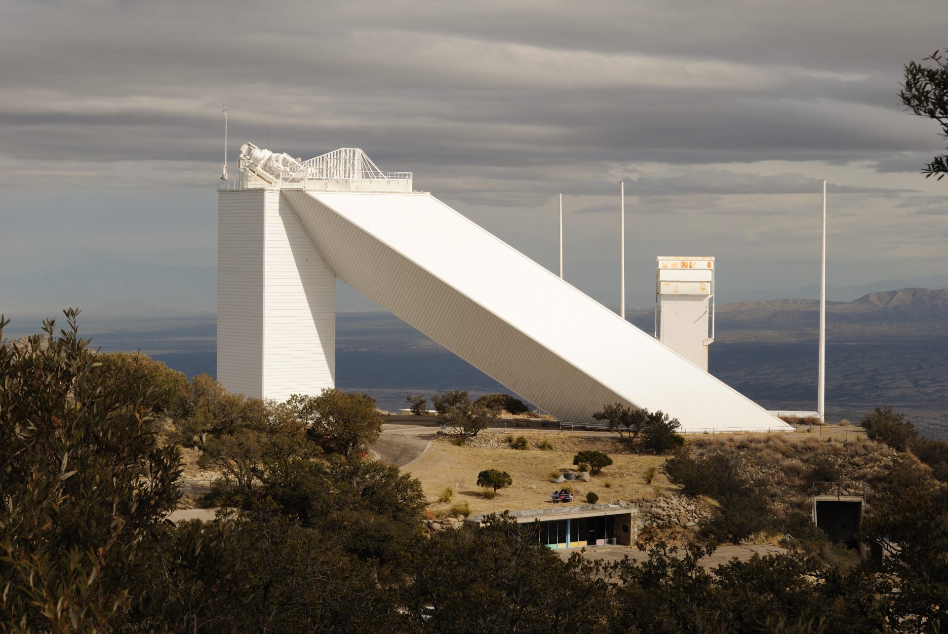
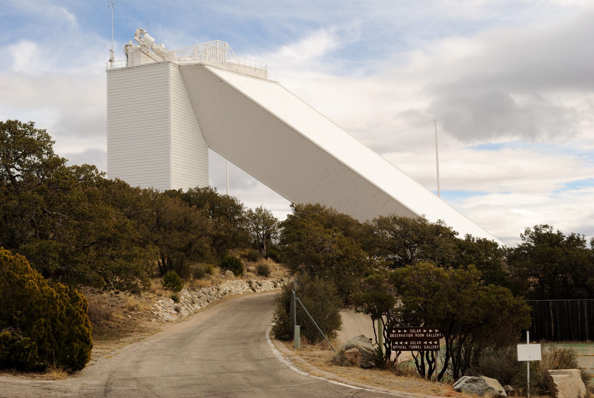
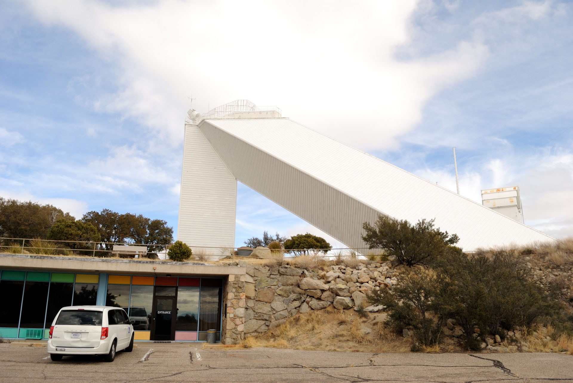
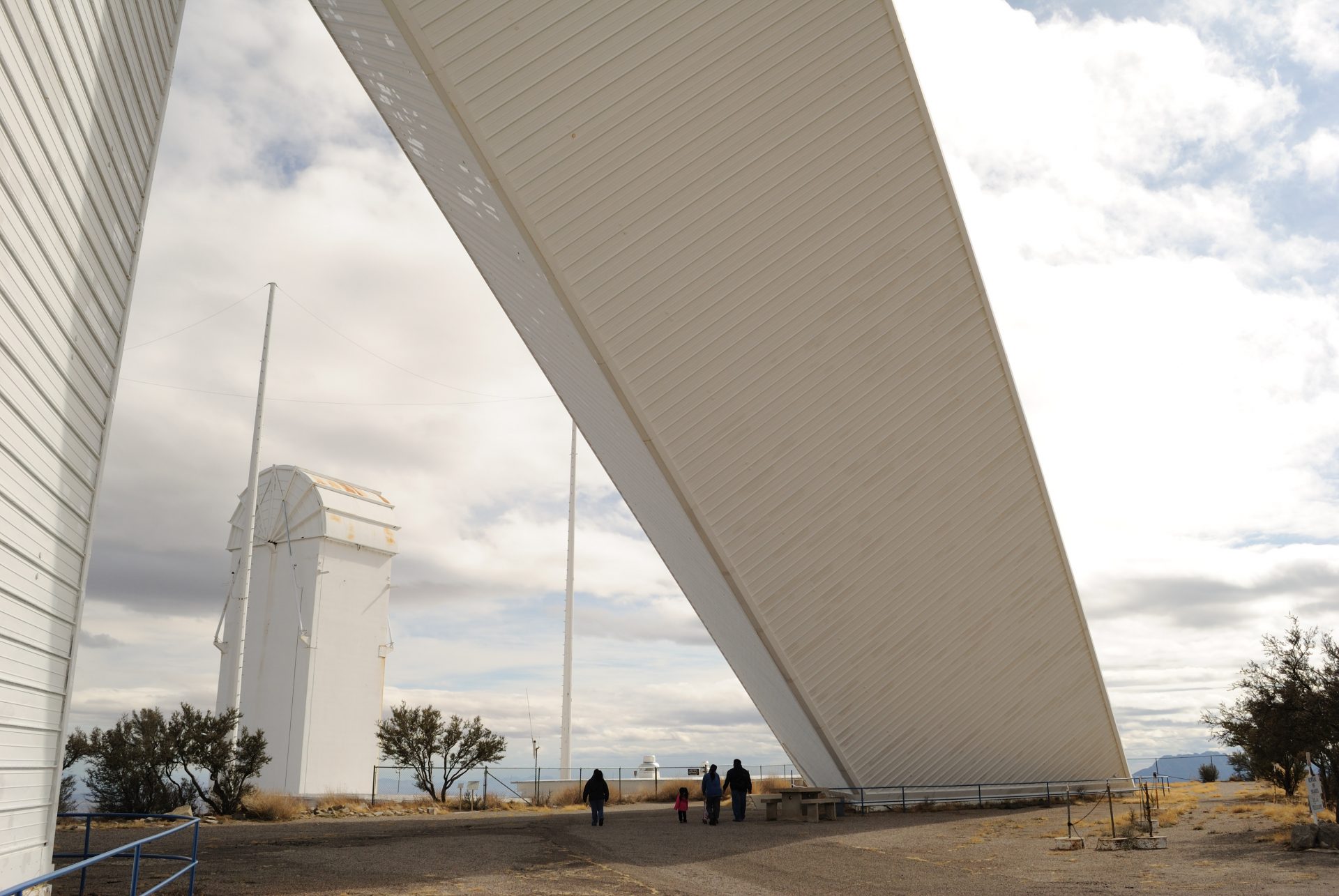
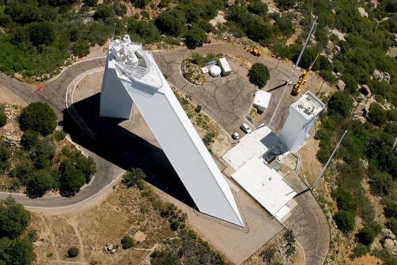
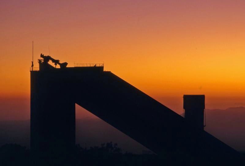
The McMath-Pierce Solar Telescope was designed and built between 1958-59 by architect Myron Goldsmith of Skidmore , Owings & Merrill, taking into account the previous designs made in 1957 by the civil engineer William F. Zabrinskie. At the time of its completion it was the largest built instrument dedicated to seeing and studying the sun. Its inverted V shape can be seen miles high on the National Kitt Peak Observatory.
During his inauguration in 1962, President John F. Kennedy defined the McMath-Pierce Telescope as “…bold in concept and magnificent in its execution…”. In addition to enabling the advance of studies of the sun, the telescope has become one of the most photographed sculptural outdoor monuments in the area.
However, as years passed and technological advancements were made, the National Solar Observatory moved its headquarters from Tucson to Boulder, Colorado. The organization abandoned its solar telescopes here and in New Mexico for a larger instrument in Hawaii, the Daniel K. Inouye Solar Telescope on Maui, operational since 1919.
Location
The telescope is situated at the Kitt Peak National Observatory, 2,096 meters above sea level in the Quinlan Mountains, amidst th Sonoran Desert, Arizona, United States, west of the city of Tucson.
Site selection
The search for the “world’s largest Solar Astronomical Telescope” began in 1955, limited to the Southwestern United States: California, Arizona, New Mexico, Nevada, Utah, and Texas. The terrains were surveyed by land and air, narrowing down to 150 potential sites. These were further explored using jeeps and on foot. At the end of this survey phase, only five candidates remained.
Test towers were erected at these five sites, equipped with instruments to measure sky transparency, humidity, winds, and temperature fluctuations. Two sites in Arizona emerged as most suitable: Hualapai Mountain southeast of Kingman and Kitt Peak, 70 km southwest of Tucson. The final report in March 1958 showed Kitt Peak as the clear preference over Hualapai. Both sites were similar in rainfall accumulation, transparency, and light pollution. Hualapai had a slight advantage in clear nights, but Kitt Peak offered superior visibility, lower winds, better temperature stability, and fewer aircraft vapor trails.
Concept
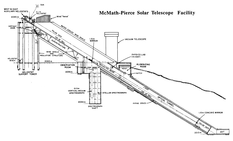
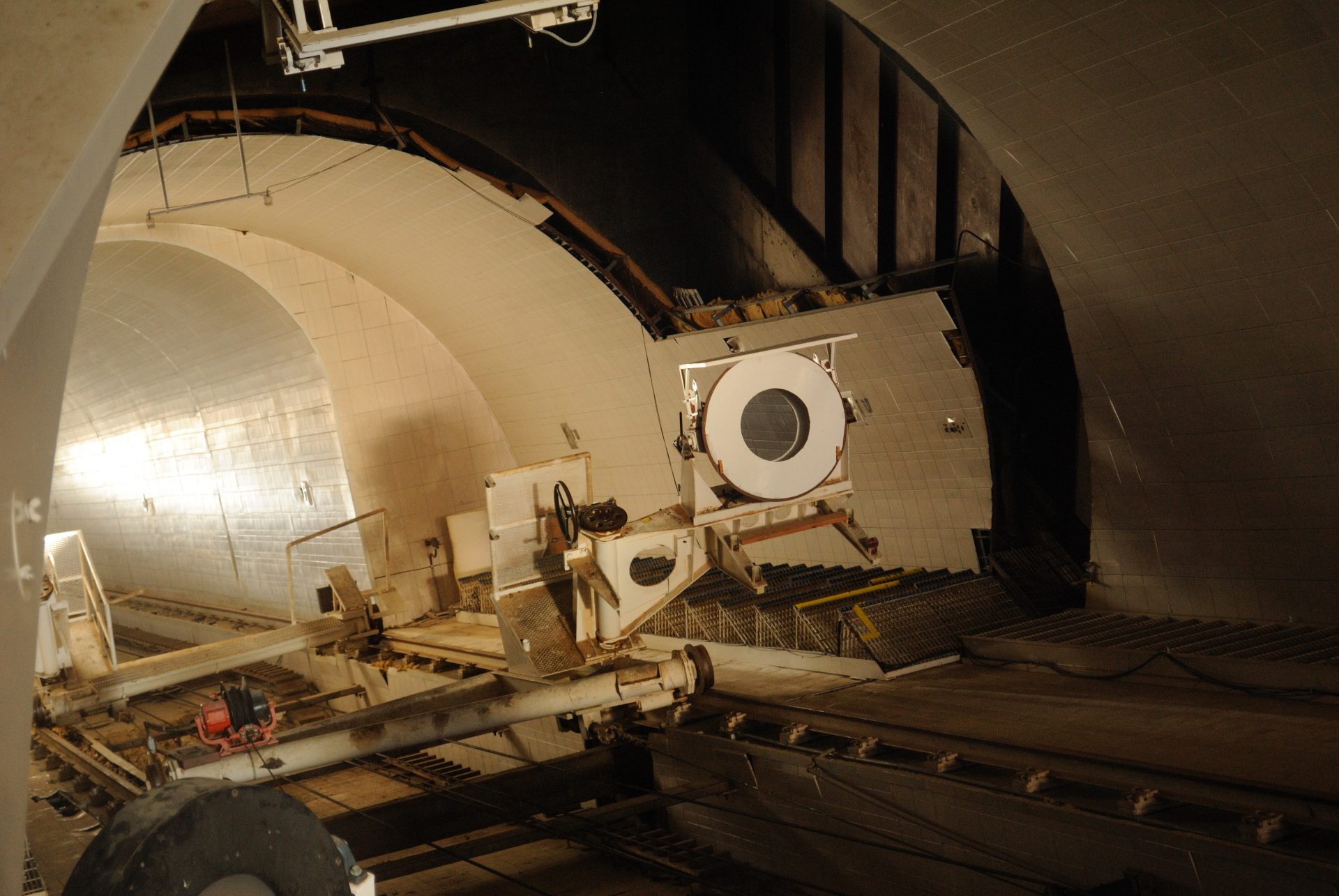
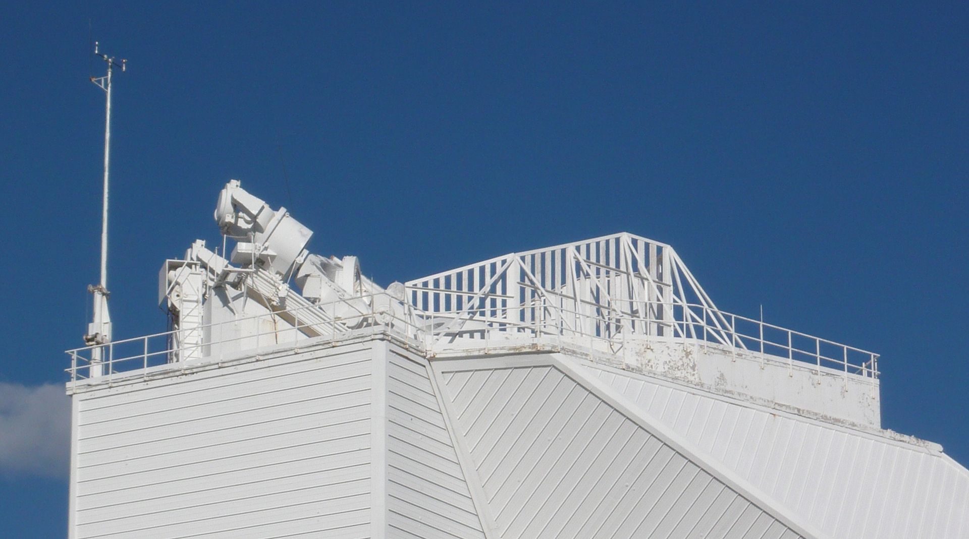
The main instrument of the building is a heliostat, tracking the sun across the sky and focusing its light downwards through the diagonal axis. This axis continues some 50 meters vertically underground to a 1.6-meter primary mirror, forming the largest unobstructed aperture of any optical telescope system. From here, the light travels back a portion of the axis to a flat mirror, reflecting an 85 cm wide image of the sun downwards to an underground laboratory.
Besides being the world’s largest solar telescope, the McMath-Pierce is unique for being sensitive enough to observe bright stars at night. The telescope also features a low-cost adaptive optics system. Using a rapidly deformable mirror to correct atmospheric turbulence-induced distortions, sensors measure the image’s distortion degree, and the adaptive optics system adjusts the mirror shape accordingly, turning a blurry image into a clear one.
A primary study area at the observatory is the structure of sunspots, relatively cool, dark spots on the sun’s surface caused by intense magnetic activity. Key discoveries at McMath-Pierce include detecting water vapor on the sun, measuring kilogauss magnetic fields (thousands of times stronger than Earth’s) outside sunspots, and detecting a natural maser (like a laser but with microwaves instead of visible light) in the Martian atmosphere.
Engineer Zabrinskie, responsible for the original design, thought the telescope’s triangular structure resembled the hand of a giant sundial. Hence, he referred to the telescope building as the “Index Building.”
Building design operation
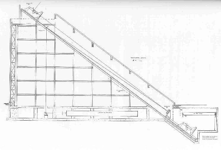
In 1957, civil engineer William F. Zabrinskie was commissioned to prepare three preliminary designs for the solar telescope
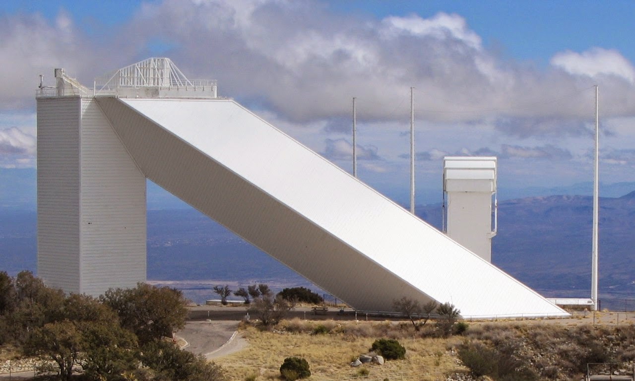
building. These designs were conceptually similar, all appearing as large right-angled triangular structures with the heliostat mounted at the top of the vertical section. The heliostat beam shines down the hypotenuse of the triangle, aligned along the telescope’s equatorial axis. The image, mirror No. 2, is located at the bottom of the hypotenuse, reflecting back up to the foldable flat mirror, No. 3, situated just below the heliostat. This placement ensures an unobstructed optical path. Mirror No. 3 diverts the beam downward to an air-conditioned observation room just below ground level. Spectrographs and other instruments are mounted horizontally in the observation area along the base of the triangle.
The differences between the three designs primarily concerned the framing style. One design used H-beams and columns, another large steel tubes, while the third was intended for reinforced concrete construction.
It’s noteworthy how many of Zabrinskie’s preliminary design concepts were incorporated into the final telescope structure. The final design retains the general triangular shape. All optical supports were placed on rail-like tracks for mobility in focusing and servicing. The structure’s exterior was designed to act as a wind shield and was water-cooled. These ideas from Zabrinskie’s designs are evident in the telescope’s final structure.
Final design
Following the preliminary design work of Zabrinskie, AURA (Association of Universities for Radio Astronomy) hired the Chicago firm Skidmore, Owings and Merrill to study all possible structural designs for the solar telescope. These studies should include, but not be limited to, the designs made a year earlier by Zabrinskie.
Skidmore, Owings and Merrill prepared ten designs for the construction of the telescope. Of these ten, they recommended two for final consideration by AURA. One consisted of a conical cantilever tower that extended from the ground at the local latitude angle of 32 °. This design has been described as an “extreme case of the leaning tower of Pisa” (Kloeppel 1983). The design may have been aesthetically beautiful, but more expensive and less stable than the simplest tower structure that was adopted by AURA in June 1959.
Structure
Tower
Optical configuration
The initial step in designing the new solar telescope was determining the optimal image scale. Working on the spectra of solar granules, the physical structure of sunspots, and their associated magnetic fields requires a considerable image size. Previous experience has shown that the optimal solar image should be about 0.91 m in diameter (McMath and Pierce 1960). Various optical designs for the solar telescope were considered.
Heliostat
The heliostat configuration was ultimately chosen for the solar telescope. The heliostat uses only one mirror to track the sun. The mirror is mounted equatorially and rotates with the celestial sphere once per day. The heliostat can also be moved in declination. This mirror setup reflects the solar beam down the telescope’s equatorial axis to the stationary imaging optics, thereby requiring relatively simple mountings.
The downside of a heliostat is its rotating image once per day. To compensate for the rotation, instruments must be built to rotate at the same speed. This complication was deemed a small price to pay for the other virtues of the heliostat: a single moving mirror system without shadowing during the day’s observation.
Materials
The structure primarily used reinforced concrete and steel in its construction.
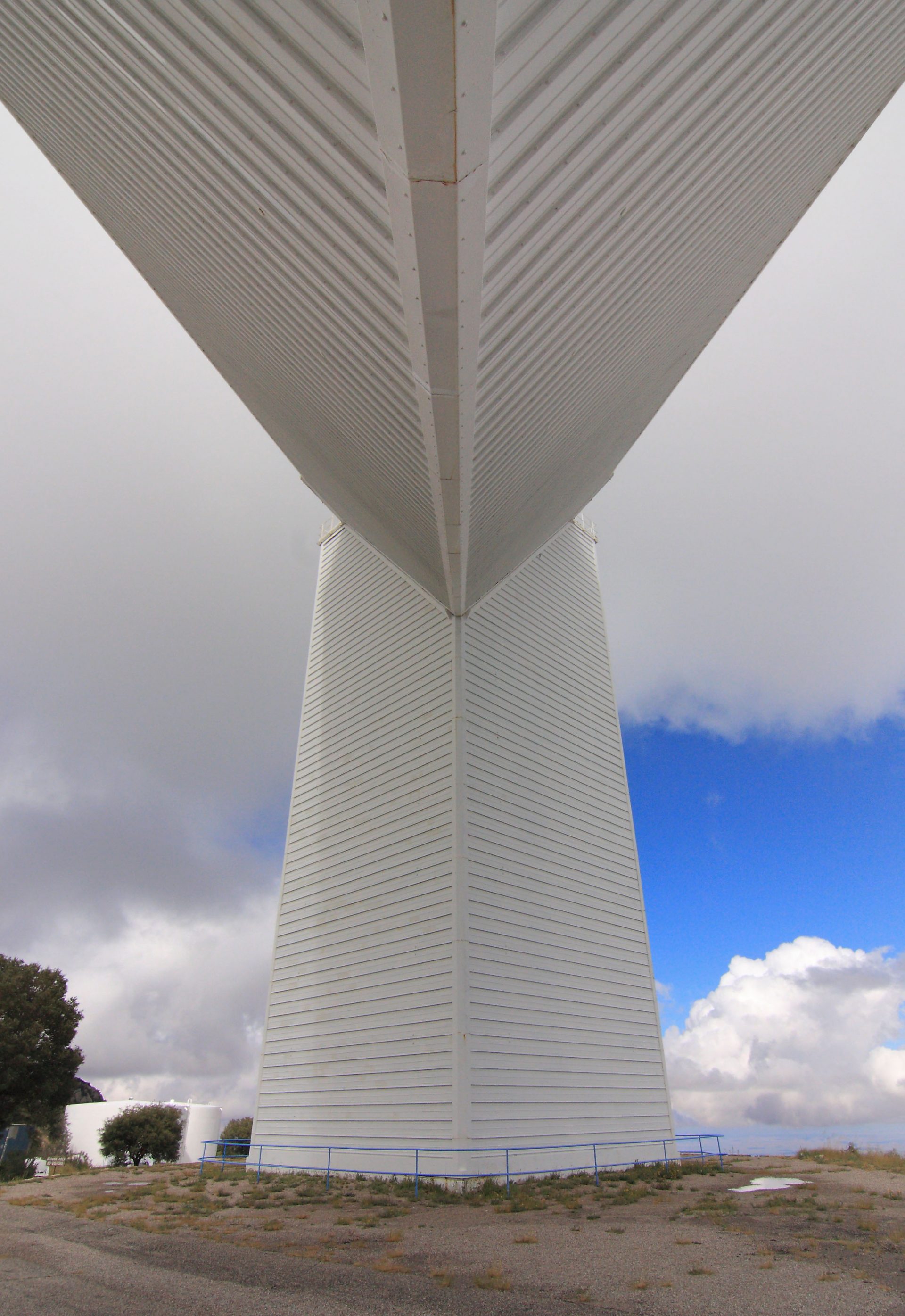
In the final optical design, the heliostat is positioned atop a solid concrete cylinder, 7.92m in diameter with 1.22m thick reinforced steel walls.
The strategy to deal with the telescope’s excessive heat load was separated into two independent cooling systems, one for the underground optical tunnel and the other for the above-ground structure.
Optical tunnel cooling
About two-fifths of the telescope’s path was excavated underground. The optical tunnel was cut through the mountain’s south side downward at a 32-degree angle (the local latitude) to point towards the celestial north pole. The lower, southern end opens to the mountain’s south slope. Fans were installed at the lower opening to allow outside air into the telescope from the top and be expelled through the southern end opening.
The rock surrounding the optical tunnel maintains a fairly constant temperature of around 13°C year-round. It was found that this temperature was low enough that no additional cooling was needed to stabilize the view in Arizona’s warm summers. Winter ambient temperatures can fall well below freezing for extended periods, so a cooling system was designed and installed.
The walls of the underground optical tunnel are lined with about 18,000 m2 of aluminum panels, connected to a network of over 7,500 meters of 2.5 cm diameter water pipe. 7.6 cm thick insulation was installed between the cooling pipes and the tunnel’s rock wall. The water pipes circulate a chilled 42% glycol and 58% water solution cooled by a 3-cylinder compressor. The glycol/water solution enters the pipe grid at the bottom of the optical tunnel and exits at the top. The liquid’s temperature will consistently warm as it ascends the telescope’s optical path, absorbing heat from the surrounding rock. This consistent temperature rise is exactly what’s desired to create a stable air mass along the optical route. The cooling system is turned off during the summer months. In winter, internal and external temperature indicators regulate the compressor to maintain the tunnel walls at the appropriate temperature.
Cooling structure on the ground
The above-ground structure of the McMath-Pierce Solar Telescope is covered by approximately 2,787 square meters of panels. Various materials and paints were evaluated to test their heat absorption from sunlight. It was discovered that a surface painted with white titanium dioxide pigmented paint heated up only between 5.6 to 8.3 °C in full sunlight (McMath and Pierce 1960). Copper was chosen as the material for the panels due to its very high thermal conductivity. Even so, it was estimated that during midday, the sun would heat the skin panels with approximately 23.45 kilowatt-hours in the winter and nearly 41 kilowatt-hours during the summer months (Donovan & Bliss 1962).
The copper panels used to cover the telescope include built-in 1.27 cm diameter water lines known as “Tube-in-Strip.” The “Tube-in-Strip” exterior panels were coated with white titanium dioxide pigment paint to minimize solar heating absorption. A mixture of glycol and water circulates continuously through the Tube-in-Strip panels. This glycol cooling mixture is pumped into a 60,566-liter retention tank. This large retention tank acts as a heat mass for the telescope. The warm liquid returning from the telescope’s skin mixes with the water and glycol in the tank and gradually heats the liquid in the tank throughout the day. The temperature of the glycol coolant flowing from the tank is delayed by a few degrees for most of the day. The cold glycol mixture enters the telescope at ground level and heats up as it advances up through the skin and returns to the tank a few degrees above room temperature. This continues the constant temperature rise within the telescope all the way to the top, where the telescope’s air mixes with the outside air with a very small temperature differential. The rate at which the coolant flows through the Tube-in-Strip panels is regulated by temperature gauges that read the temperature difference between the liquid flowing to and from the telescope.
The circulation system continues operating throughout the night. This allows the coolant, which heats up during the day, to radiate its excess heat back into the cold night sky. By morning, the temperature in the tank returns to room temperature, and the process is ready to start again. If the outside temperature unexpectedly rises, fans at the bottom of the tunnel can be turned on to draw outside air into the telescope through the opening at the top.
Video