


Lotus Temple (Bahá’í House of Worship)
Introduction
In the architecture of India, perhaps more than in other places, it is possible to the see the religious roots in a clear and different manner. The representative symbols which can be seen on the buildings and in their decorations, and which include the surroundings in which they have been placed, are inspired by the religious convictions of the people; convictions which are integrated and form part of the way of life of the country. The bushes which grow in the corner of a temple courtyard or the colour of its walls can indicate to us to which religion the temple is dedicated. In this way we can also discover the allegorical significances which the forms, colours or statues wish to convey to us, in such a way that we can consider Indian architecture as an architecture of story-telling and symbols, in which hidden meanings dwell in every form. These hidden meanings have an intimate and inspired connection with the lives of the people of this place.
Project
In 1976, the international governing body of the Bahá’í community, the youngest independent religion in the world, chose the architect, Fariborz Sahba, to design the Bahá’í House of Worship in New Delhi, a project on which he worked for 10 years as the architect and director of the works. The Canadian architect, Arthur Erickson, described it as “one of the most noteworthy achievements of our time, which demonstrates that the unity and vision of the spirit can make miracles”. It is the principal temple of the Bahá’í faith, known as the “Lotus Temple”, “Lotus of Bahapur” or “Temple of Bahá’í”, though its official name is the “Bahá’í House of Worship”.
Location
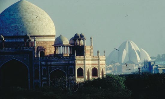
The temple was built in the village of Bahapur, Kalkaji, in the South of New Delhi and to the West of Connaught Place in Mandir Marg; a secluded area of the bustling centre of India‘s capital.
Concept
Observing Hindu architecture, you can see that despite the external difference between the various temples, they all show meaningful and sacred symbols common to all of India’s religions. These are symbols which have emerged in other countries and religions. One of these symbols is the sacred flower of the Indians: the lotus flower.
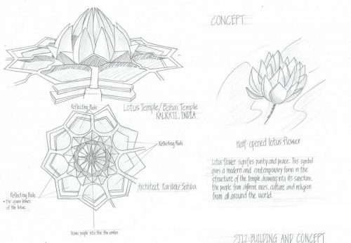
Fariborz Sahba developed the project for the temple inspired conceptually by this flower which symbolises purity and cleanliness in Hindu tradition. This concept had to be converted into defined geometric forms, such as spheres, cylinders, toroids and cones, which were translated into equations and later used as a base for the structural analysis and engineering plans. The resulting geometry was so complex that the plans for the temple took two and a half years to complete.
Influence
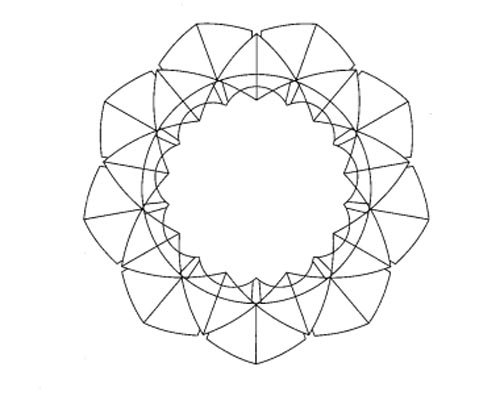
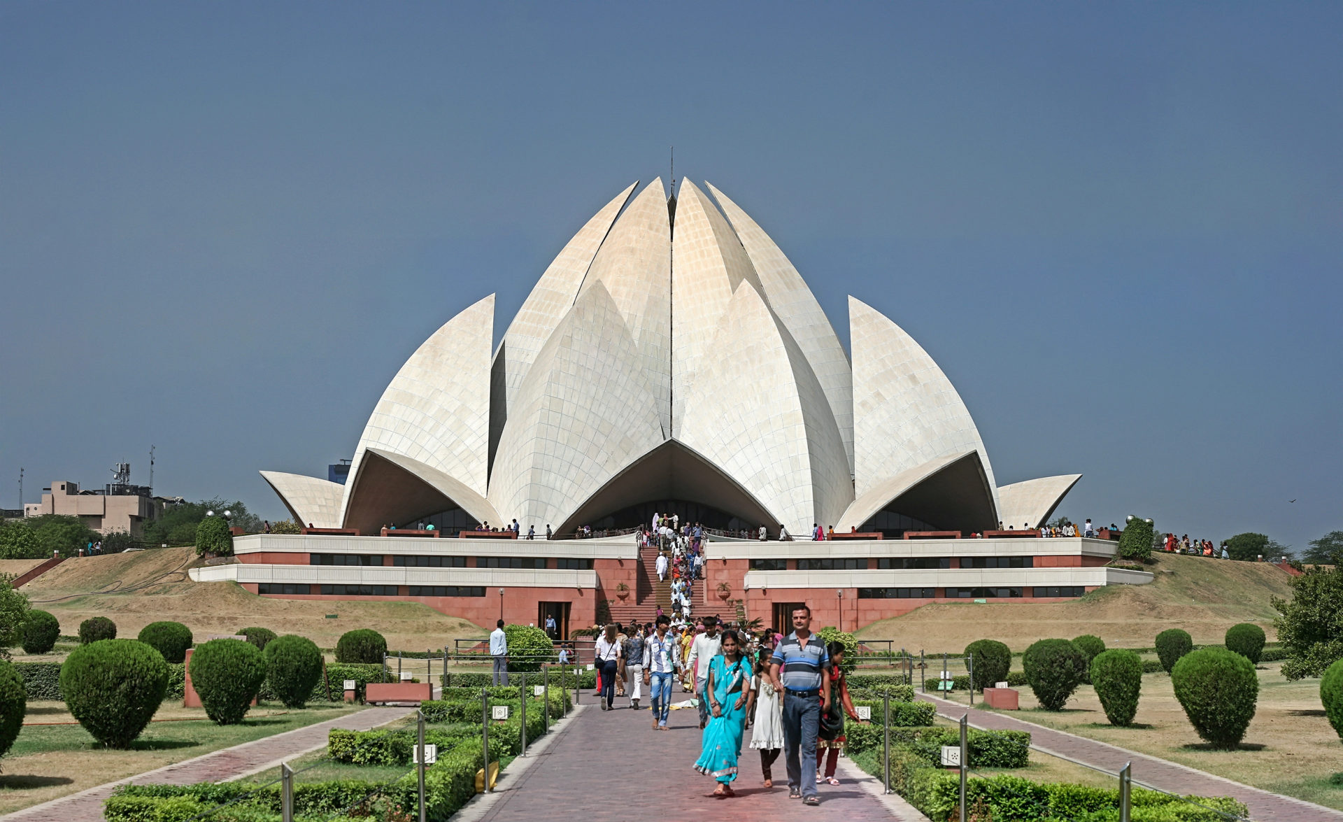
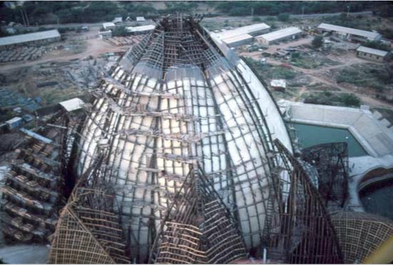
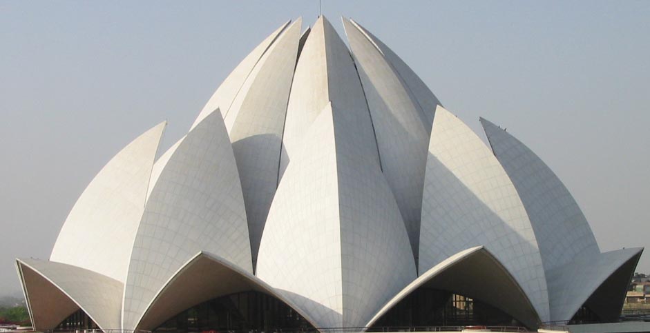
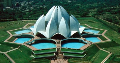
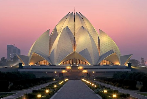
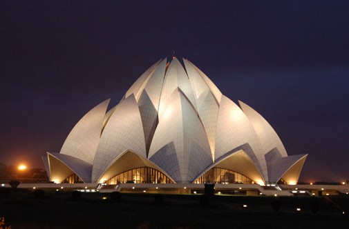
The temples of the Bahá’í faith are well known for the architectural splendour, and the temple constructed in Delhi in a continuation of this rich tradition. Before beginning the design, the architect travelled around India to study the country’s architecture and was impressed with the design of the temples, as well as the art and religious symbols, in which the lotus flower always played an important role. Inspired by this experience, and with the objective of representing the concept of purity, simplicity and freshness of the Bahá’í faith, he conceived the design of the Delhi temple in the form of a lotus flower. The temple gives the impression of a semi-open lotus, floating, surrounded by its leaves. Each component of the temple is repeated nine times. In the Hindu opinion, the lotus has always been the most beautiful flower, enjoying an unprecedented popularity throughout India since the beginning of time through to modern day, as demonstrated in both literature and art, and appearing in the oldest monuments of Hindu architecture.
Description
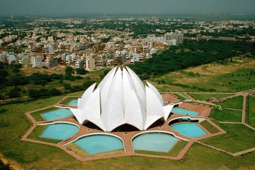
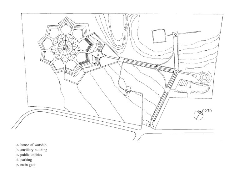
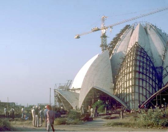
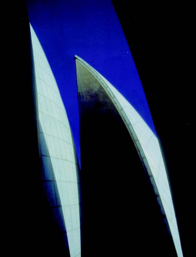
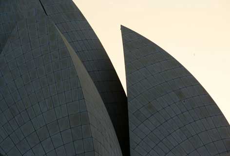
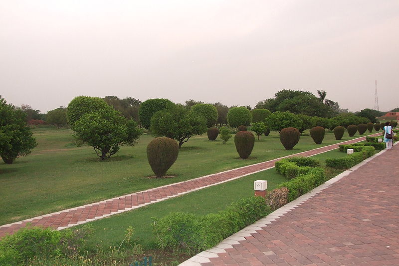
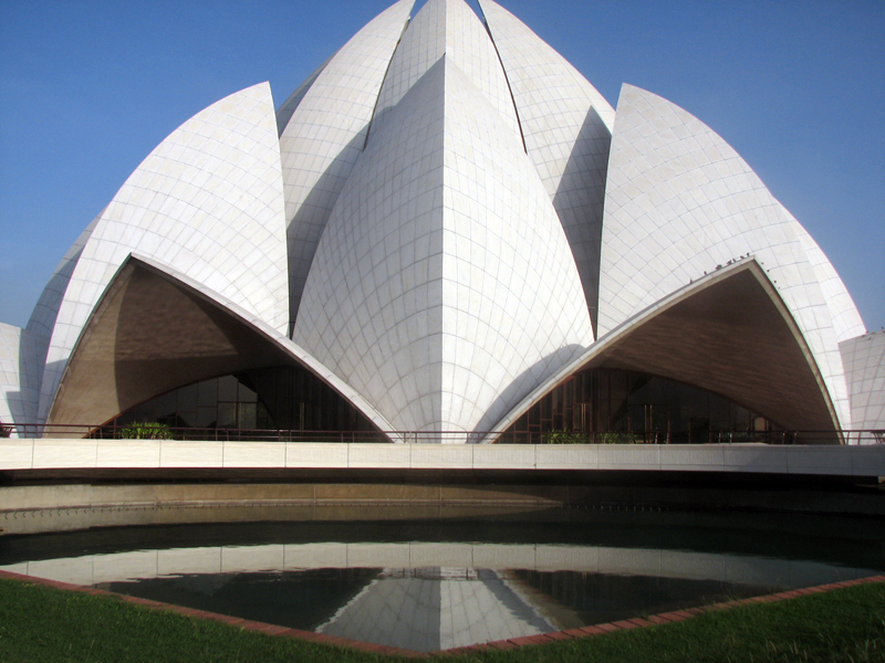
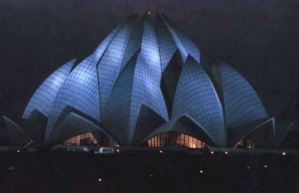
Its external structure is formed of 27 giant marble petals which envelope the interior space, respecting the circular alignment of Bahá’í architecture. The interior has capacity for 2500 people. It is accessed via nine bridges which cross nine ponds surrounding the temple and provide access to nine doors. The doorways lead to a central area which reaches 40 metres in height, though shows no visible supports. The temple is surrounded by gardens and its location in the centre of the ponds creates the impression of a giant lotus flower floating on the water. Along with the nine ponds around the temple and the gardens, the area occupied by the Lotus Temple is 105,000m². The external covering of white marble ensures the building is visible from a distance and shines with the rays of the sun, turning violet at sunset.
Structure
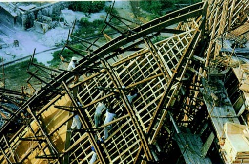
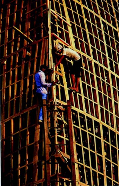
The complexity of the structure and the high level of labour necessary required a dynamic management with a high grade of innovation. One of the essential means of achieving the fixed objective was to anticipate problems in advance and to resolve them using tests and models.
The building’s twenty seven structures of reinforced concrete in the shape of petals, clad in marble, were arranged in groups of three, to create the nine faces. All Bahá’í Houses of Worship share certain architectural elements, such as the circular shape with nine sides specified in Bahá’í’s scriptures. Although nowadays all Houses have a cupola, it is not considered an essential element of the architecture. The scriptures also dictate that no painting, statue, image, pulpit or altar can be added as an architectural element.
Petals of the entrance and outer leaves
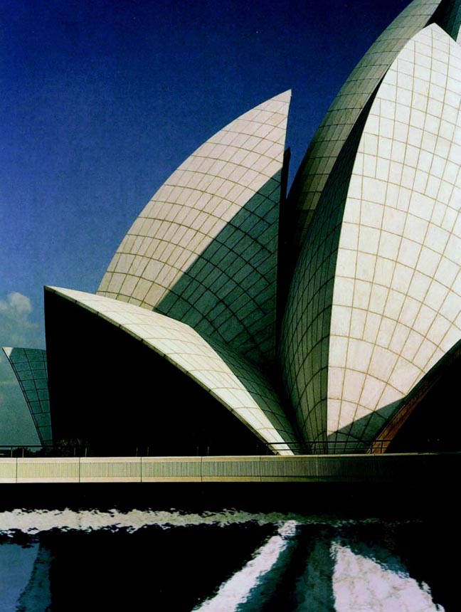
The surfaces created by the shell on each side of the entrance-ways and the outer leaves are formed by spheres of different radii, with their centres located at different points of the interior of the building. There is a group of spheres for the leaves of the entrance, some of which define the interior surfaces and others which define the exterior surfaces of the shells. The diameters of the spheres have been fixed to satisfy the structural consideration of the varying thicknesses of the petals.
For the outer leaves, another group of spheres define the interior and exterior surfaces of the shells, but in this case the thickness of the shell is uniform: 1.33m thick toward the lower part and 2.55m toward the upper extreme. The outer leaf in the entrance zone to the temple is 15.4m wide and rises 22.5m above the podium. The interior is 18.2m wide in the entrance area and rises 7.8m above the level of the podium.
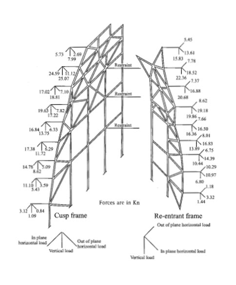
Inner leaves
Each inner leaf is composed of a cusp (edge) and a new re-entering (valley), made of two toroidal surfaces. A toroid is generated when a circle of a given radius, ‘r’, revolves around the centre of a circle with a much larger radius, ‘R’. A bike tyre is a typical toroid (doughnut). The shaded part of the toroid is part of the covered interior of the leaf.
The inner leaves, with a uniform thickness of two metres, rise to a height of 34.3 metres over the interior platform. At the lower level of each leaf, the maximum width is 14 metres.
Th Arches
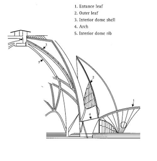
Almost the entire structural load of the temple’s interior space is supported by nine arches which spread out around the central hall, located at angular intervals of 40°. The forms of these arches are created by flat, conical and cylindrical surfaces. The intersection of these surfaces presents interesting contours and considerably improves the beauty of the arches.
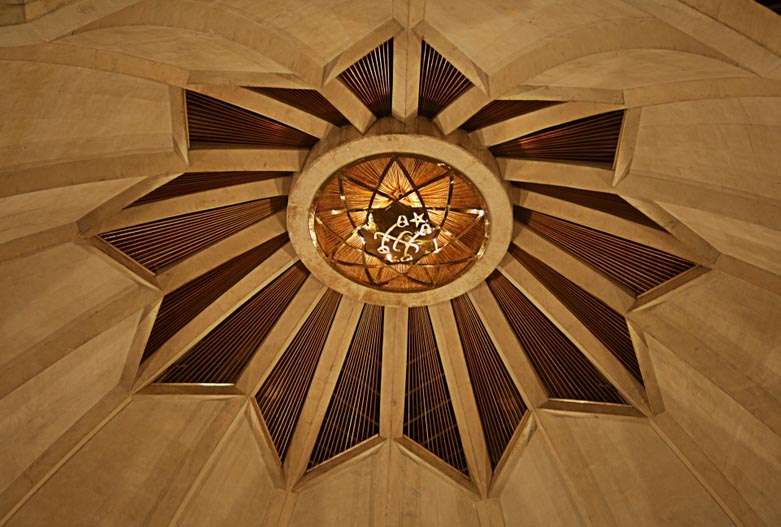
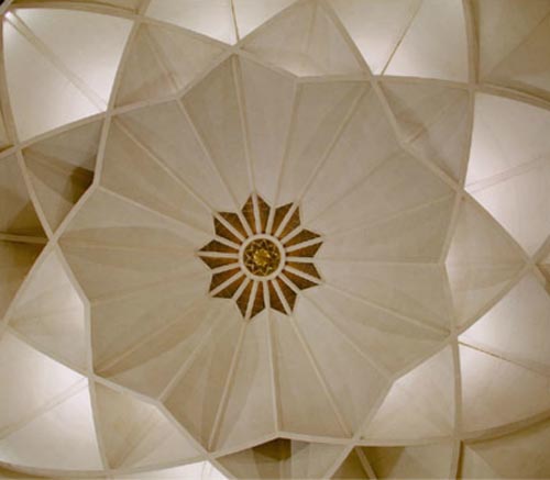
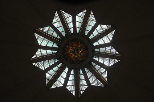
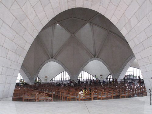
Interior cupola
Three ribs rise from the crown of each arch. While the central one, that of the dome, rises radially from the central axis, the other two (those of the base) depart from the central rib and cross over the similar ones belonging to the adjacent arcs, forming an intricate pattern. Other radial ribs rise from each of these intersections and all meet in the centre of the dome. Until a certain height, the space between the ribs is covered with a 60mm thick cladding.
Geometric adjustments
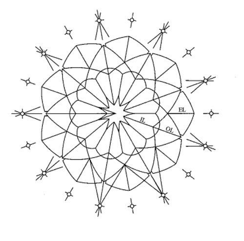
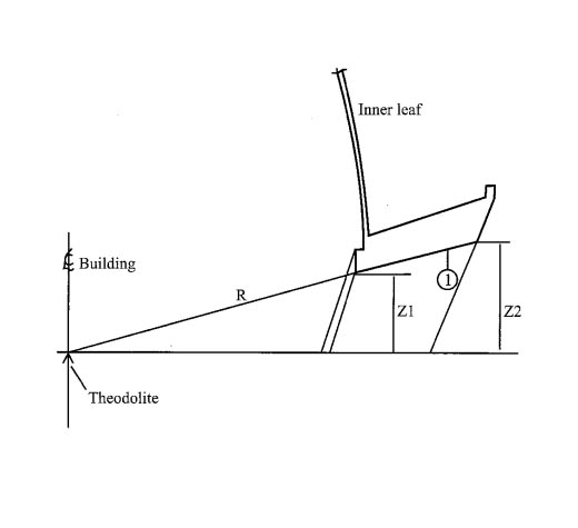
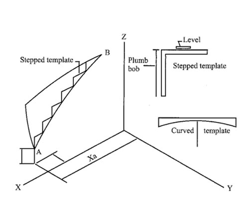
Unlike traditional structures, in which the elements are defined by the dimensions and levels, here the forms, the thicknesses, the measurements and other details are indicated in the plan only by levels, radii and equations. These parameters had to be converted into a group of dimensions in terms of length, width, height and thickness, as easy to understand for the head engineer as by the carpentry foreman. To achieve this through a system of coordinates, they used a computerised conversion system and built eighteen reference stations outside of the building to establish the parameters of the arcs of the leaves, inside as well as out, using 18 radial lines which began in the centre of the building and travelled to each of the stations. These stations were utilised to determine the lines of the apex, the entrances and the inner and outer leaves.
For example, to arrive at curve AB, the point A with coordinates XA, YA, ZA is defined in relation to 0. AB was established by means of a theodolite and the curve AB was determined by a stepped model. Curved templates were precisely made according to the requirements of the radii and were used to develop the surface between the resulting boundaries.
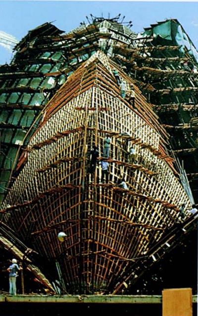
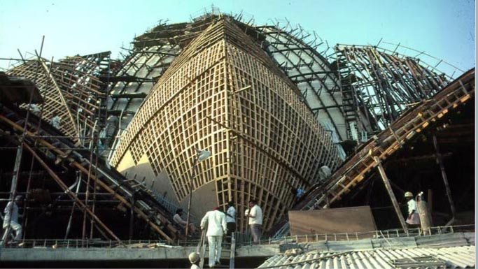
Construction

Sequence
The basement and the interior podium were first built. From there, to raise the arches and shells, the structure was divided in parts, bearing in mind that when the formwork was removed, the constructed part would support itself until the next part was complete. The structure was divided in the following way:
Arches
The nine arcs were built one after the other until the circle was complete. The dismantling of the soffit of each arch was done once the adjacent arches could provide the necessary resistance.
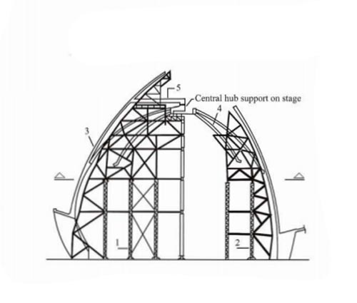
Inner leaves, radial beams and central axis
Once all the arches were completed, the interior steel structure of panels was raised. Three frames were mounted simultaneously and raised with two elevators to the level of the radial beam. The process was repeated until all nine segments were in place. The insertion of the central axis was an independent operation, after which all panels were placed to connect to the central axis through the radial beams.
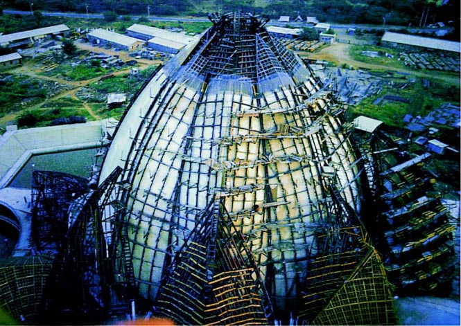
Interior dome
After fixing the interior panels, the steel cladding was modified and the folds of the shells of the interior dome were made one after the other. For each shell, three folds, the contour ribs first and then the rest of the assembly. The process was repeated until all shells were completed.
Access and outer leaves
The construction of the outer leaves in the entrance and the exterior ones were completed in tandem, along with the inner leaves and the dome. Firstly, the two leaves of the entrance and an intermediate external one were mounted. From there, they alternated the rest of the leaves of the adjacent entrances and the exterior ones. As the concrete set, the formworks were removed and moved to the next set of leaves.
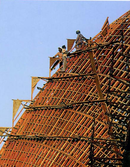
Staging and formworks
Deviation was an important consideration in the design of the formworks. The maximum permitted deviation was three millimetres per metre, including any manufacture or assembly errors.
For the assembly of the formwork of the leaves and interior dome, they had to keep in mind the following factors:
- The cementing of the storerooms had to be done three at a time, in a way in which the lateral loads of the individual supports of the formworks would be reduced as much as possible. Once completed, the concrete external surfaces were covered with burlap and cured for 28 days, keeping them continuously wet by means of a fixed sprinkler system in the upper part of the shells.
- Construction joints were to be avoided as much as possible, in order that the exposed concrete surface would show no other lines apart from the architectural pattern. In the inner interior panels, the construction joints were located above 24.8 metres.
In the interior dome, the formworks were designed in such a way that the wooden beams would support the panels, rather than the usual way, in which it would be supported by the steel structure. The interior formwork of each petal was fixed from the base up, taking into account that they must stay perfectly aligned.
Materials
The temple is constructed from marble, cement and sand. The 27 petals were clad with marble from Rajasthani Macrana, the dolomite clay is from the mines of Alwar, near Delhi, and the white silica sand is from Jaipur. The structure is cement and is combined with the pre-fabricated pieces, also cement, of the fluted petals.
Various alternatives were considered for the steel staging of the structure, considering that the structural steel frames with bolted joints would be best, and taking into account the high level of precision required for the manufacture and assembly. The interior surfaces of all the shells have a uniform bush-hammered surface of exposed concrete in which the architectural pattern can be seen. In the interior panels, this pattern is formed by intersecting vertical and radial planes. On the outer leaves and entrances, as in the interior dome, the patterns are formed by the latitudes and longtitudes of the spheres.
All the beams of the shells up to the level of the radial beam are white concrete. To avoid cracks and fissures caused by retraction, a mixture of M 30° and white concrete was applied, keeping in mind that the content of cement must be less than 500kg/m³ and the water content be reduced to a minimum.
The reinforcement used in the structural framework of the white concrete shells, as well as the connection cables, is galvanised to prevent long-term oxidation. To avoid the appearance of “covering blocks” for pieces which would cover the exposed surface of the shells, the internal layer of reinforcement is kept in position using special steel spacers supported by the exterior formwork.