


CCTV Headquarters
Introduction
In order to support the growth of China Central Television (CCTV), an international competition was established in 2002 to design a building that would serve as its headquarters in Beijing. The winning team consisted of architectural firm OMA, lead by Rem Koolhas, and engineering company Arup, accompanied by the Architecture Design Institute of East China.
The CCTV’s structural design proved difficult for an International team to manage, as they had to work with people from all over the world, who often ran into different time zones and cultural differences. Even with these challenges, the team was able to come together and present a complex design in time that was approved by Chinese Ministry of Construction.
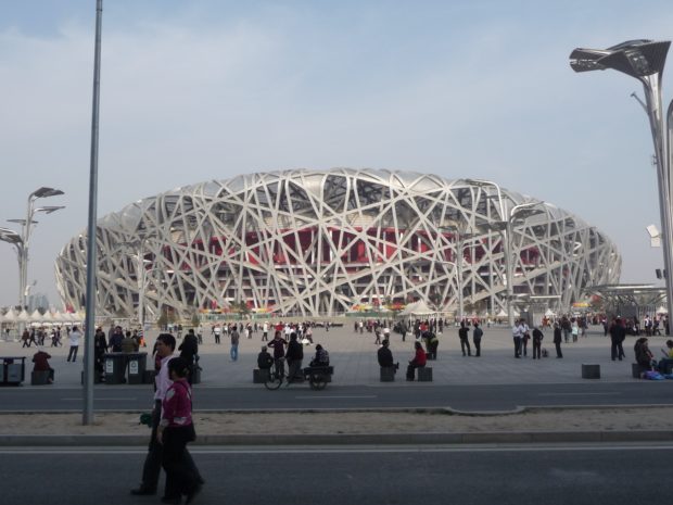
CCTV headquarters was officially opened by the President on January 1, 2008, during the 2008 Beijing Olympics, although the works were not completed until May 2012. The project began on September 22, 2004, once the design was inspected by Chinese experts, this being a venture of the government, as part of a redevelopment plan of the capital, focusing on innovative and functional architecture, preserving same time, historic buildings.
The construction of the CCTV headquarters started on September 22, 2004, and was officially opened by the President on January 1, 2008 during the Beijing Olympics, although the building wasn’t fully finished until May 2012. This was a government lead venture, as part of a redevelopment plan that focused on innovative and functional architecture while preserving historic buildings at the same time.
The design was created in 2002 by Dutch architect Rem Koolhaas and German architect Ole Scheeren from Office for Metropolitan Archtiecture (OMA). Ove Arup, the engineering contractors responsible for the building’s structure, were also in charge of safety, performing risk analysis and designing security systems.
Location
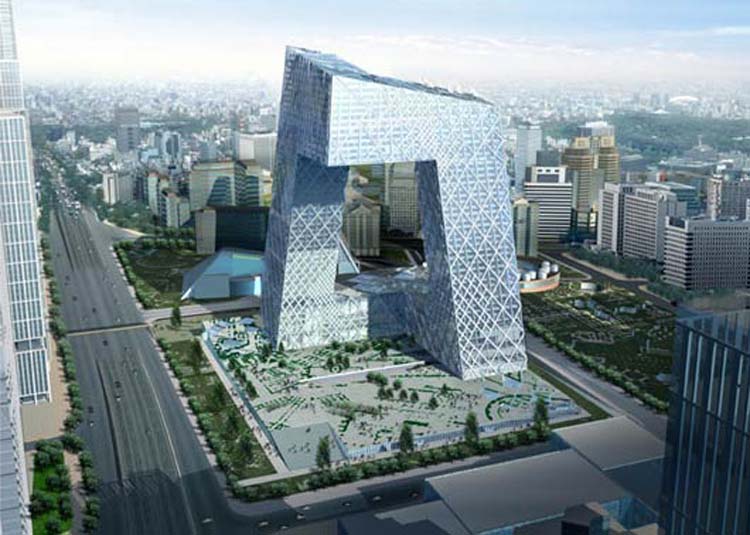
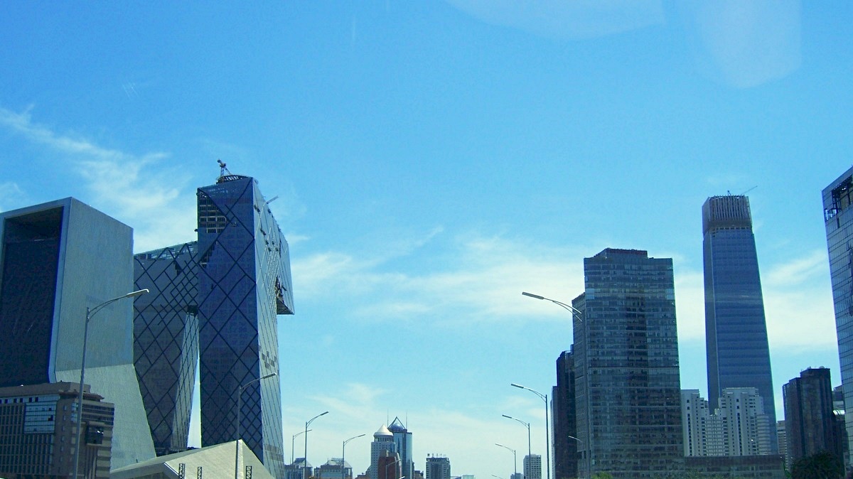
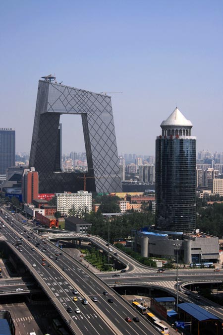
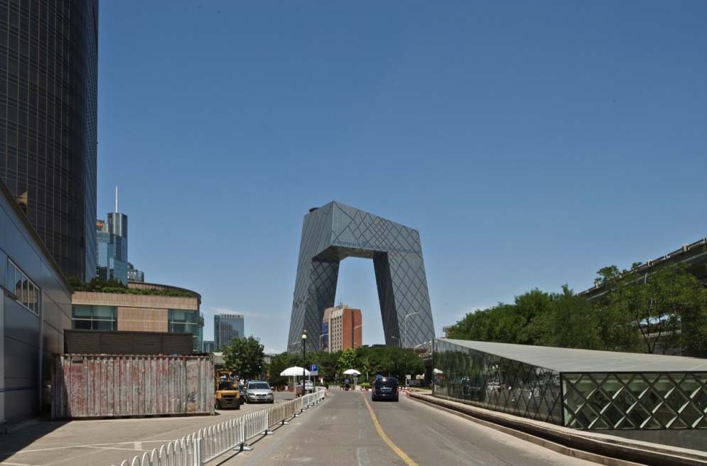
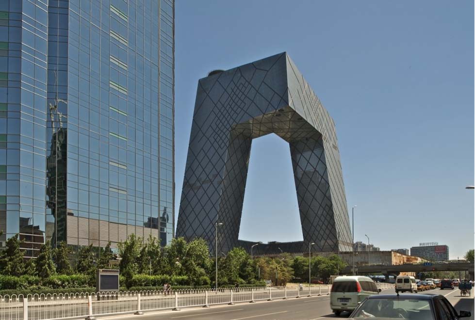
The mega-structure was built at the foot of the Third Ring Road East Beijing, Guanghua Road, China, on a plot of 20 hectares, in the new Central Business District Chaoyang, 32 号 东 三环 中路.
The CCTV building was designed as a larger project to accommodate the media, containing areas for outdoor filming and production studios. The CBD (Central Business District) contains a central green axis, which the design of the CCTV building aimed to extend.
Concept
Koolhaas imagined a building whose three dimensional form would allow the CCTV staff to perform the functions within a “continuous loop” referring to a closed circuit television, and presented the beginning of an engineering challenge.
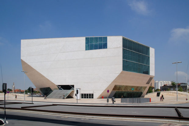
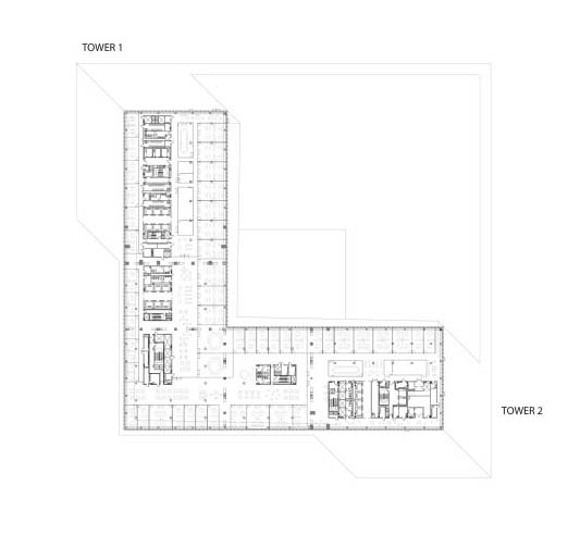
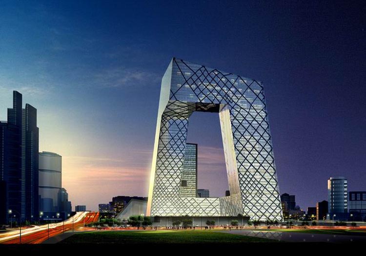
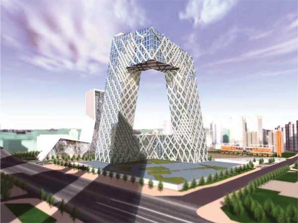
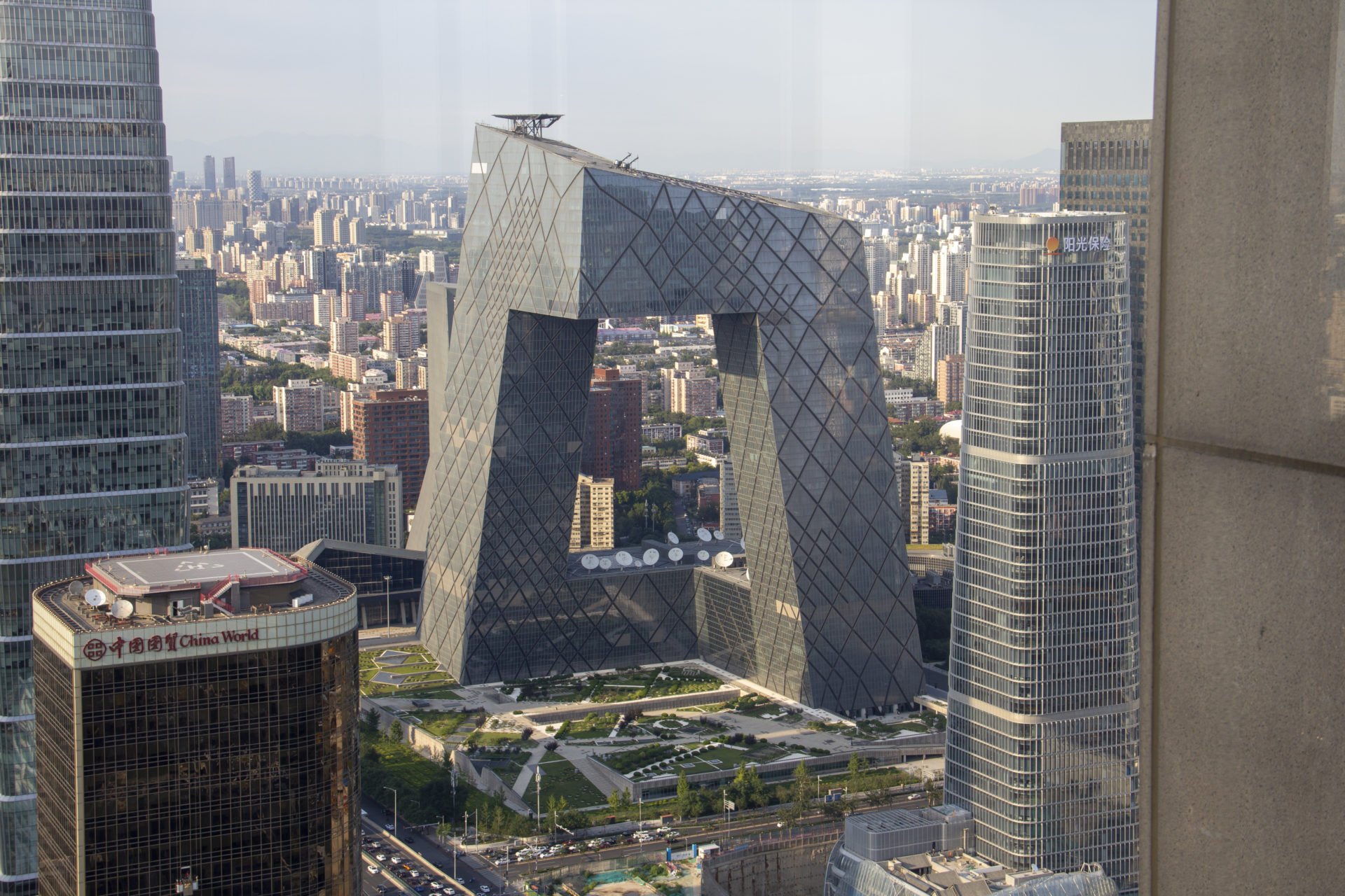
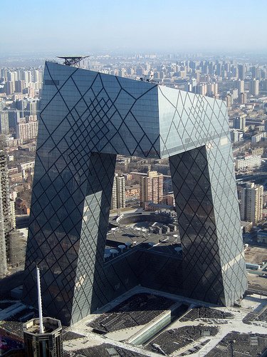
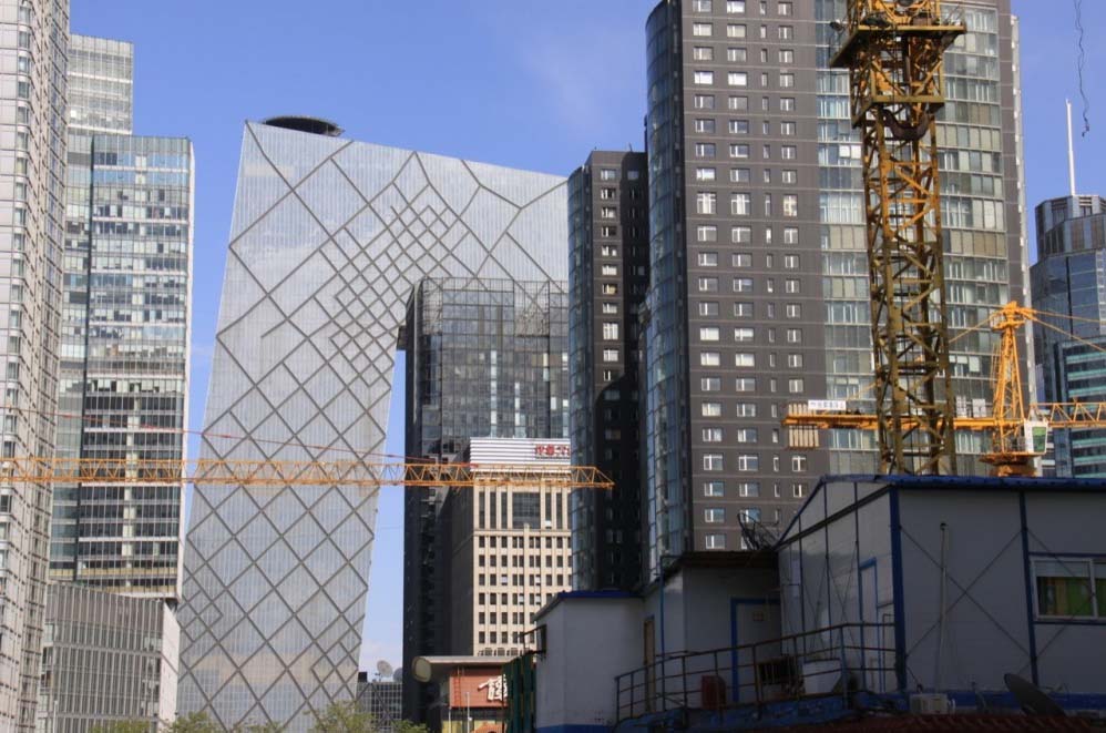
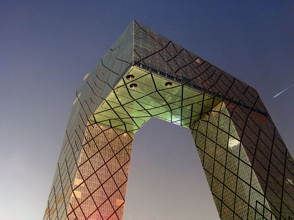
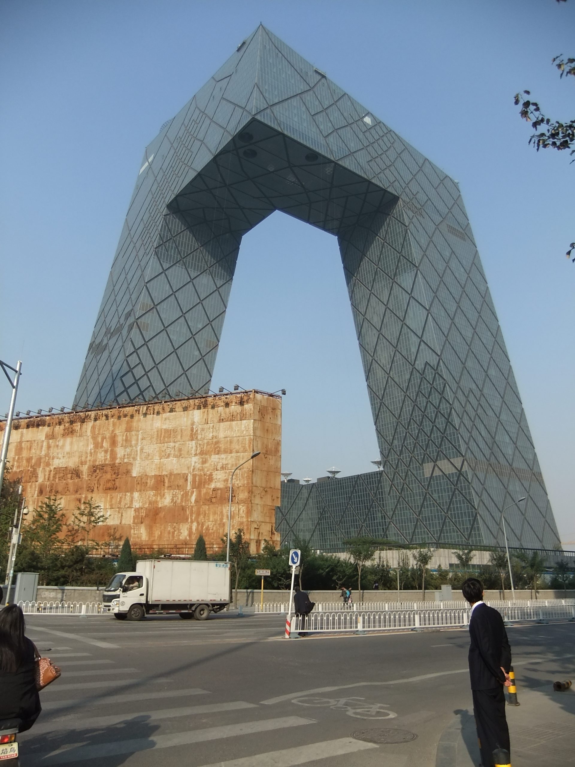
The building designed by OMA, consists of two high L-shaped towers that are joined at the top and bottom, forming a loop. This unique design has been described as a cross on Z. The construction of the building began in 2004, and it houses the headquarters of CCTV television studios, offices and broadcast facilities and production. With approximately 473 000m2 , this was the largest project designed by OMA at that time, and its first major building in China.
Spaces
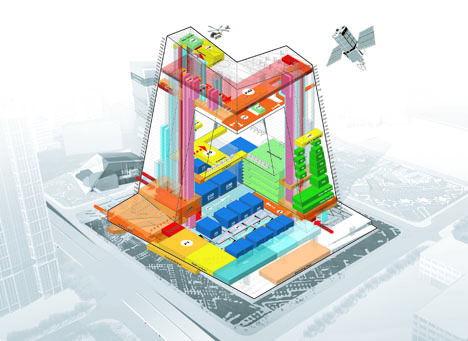
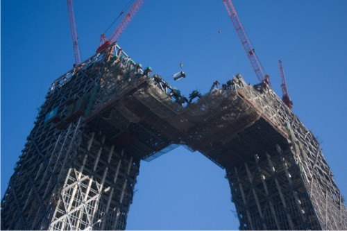
The building breaks the mold of the traditional skyscraper in its pursuit of height. Arising from a shared platform, the two towers lean towards one another before coming together in a perpendicular cantilever, 75 meters off the ground. The design brings all aspects of television work together under one roof, consolidating activities that were previously scattered throughout the city, creating a loop of interconnected activities.
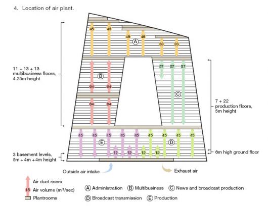
Program
- 64.200m2 administration
- 54.900m2 multi – purposes
- 65.800m2 new productions
- 31.800m2 broadcasting
- 105.400m2 production programs
- 30.000m2 staff facilities
- 61.500m2 parking
- 15.000m2 services spaces, plus a hotel, a visitor center and a large theater.
Construction
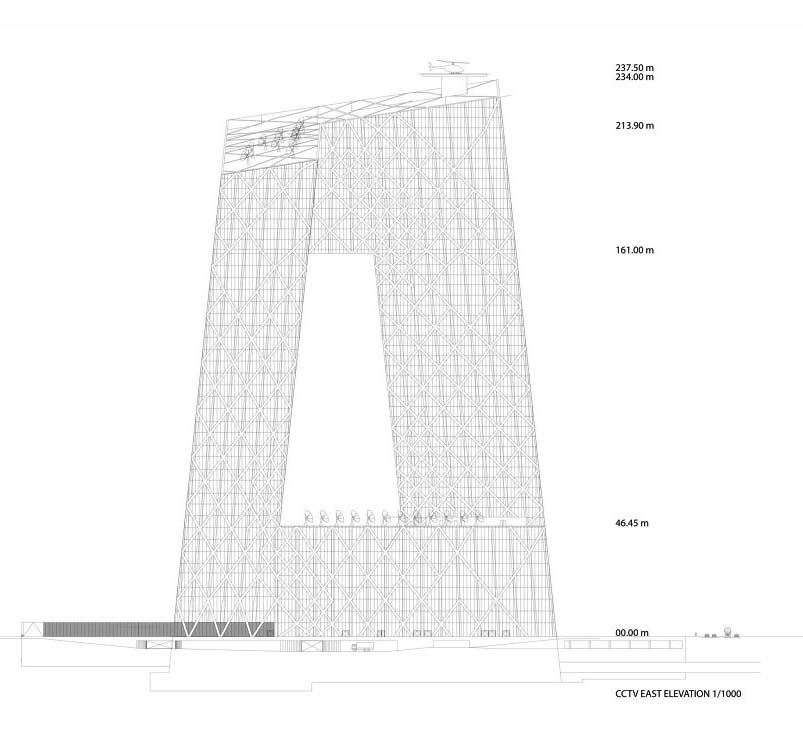
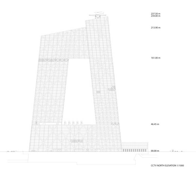
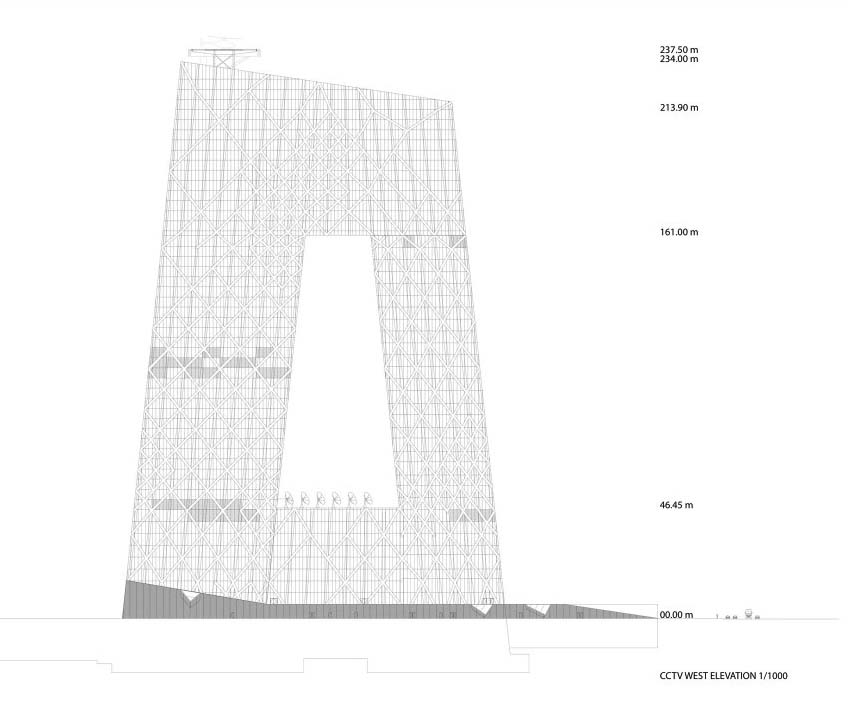
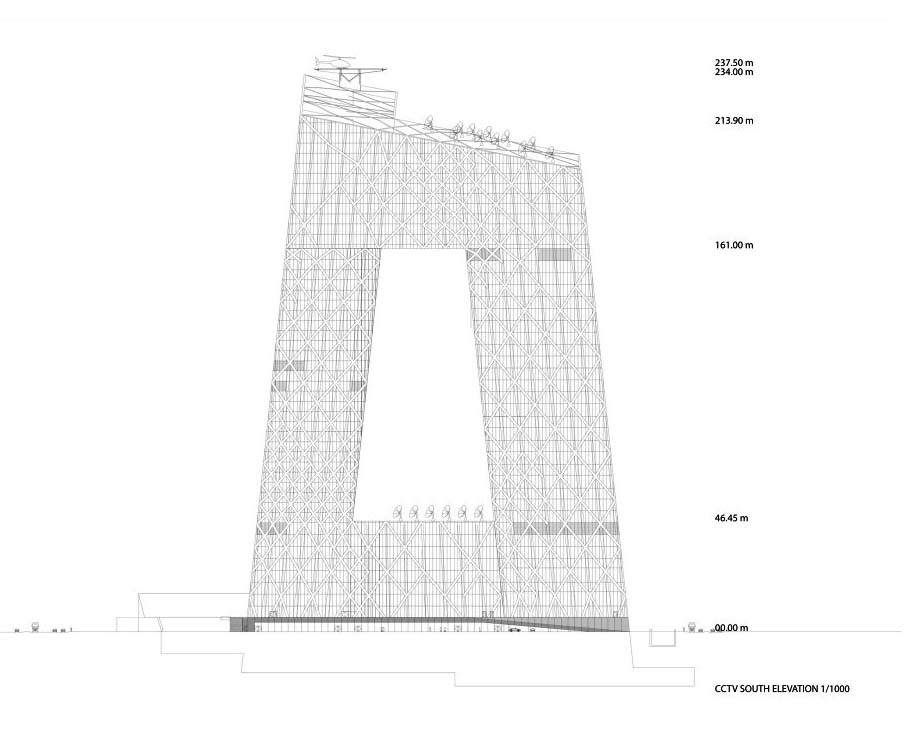
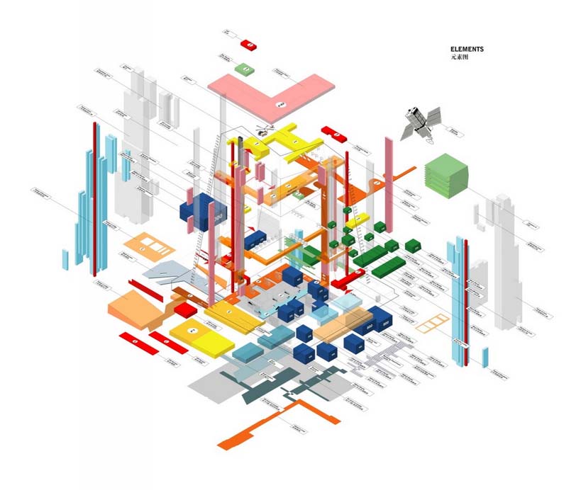
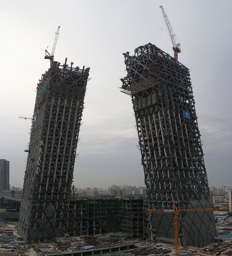
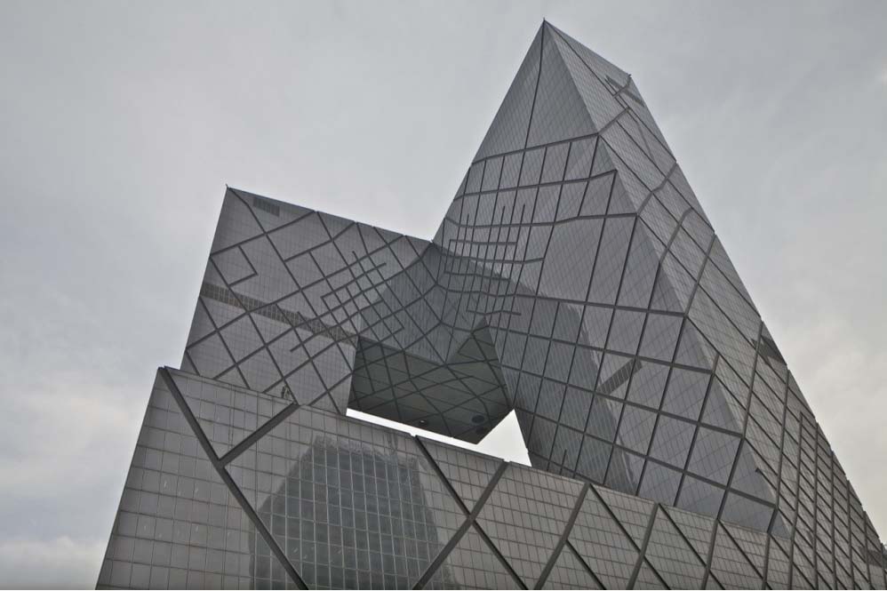
Unlike a traditional building, the CCTV headquarters is made from six horizontal and vertical sections, covering a total of 473,000 m2 of floor space. This creates an irregular grid on the façade with an open center. Its construction is considered a structural challenge, especially because it is in a seismic zone. The overhang extends perpendicularly, 75m to the west and 67m to the south.
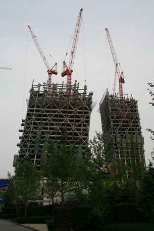
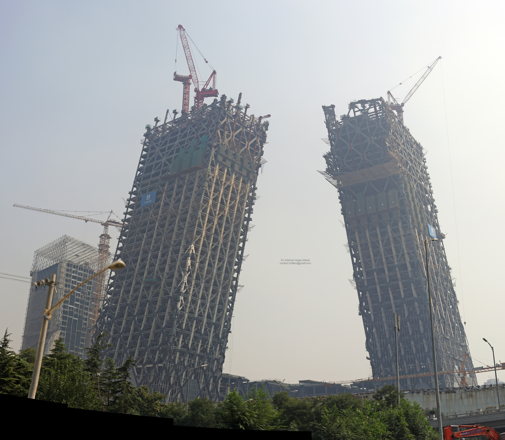
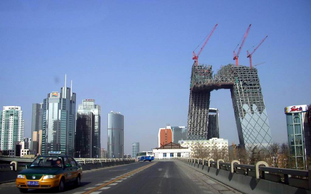
Three volumes comprising the building were joined to create a unique final volume. To avoid blocking the structural differentials, this connection was scheduled to take place at dawn, when the steel of the twin towers cooled and could be safely raised and managed at the same temperature.
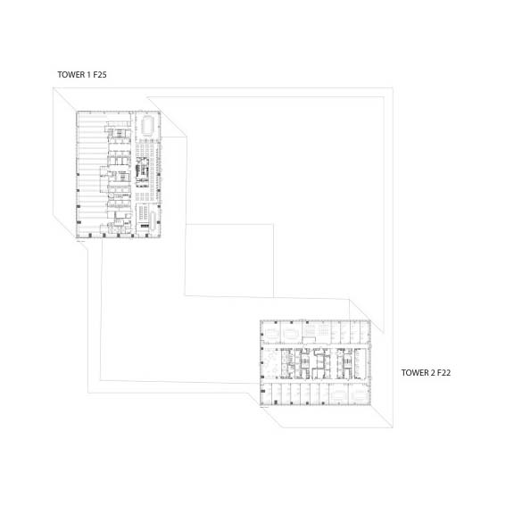
Tower 1
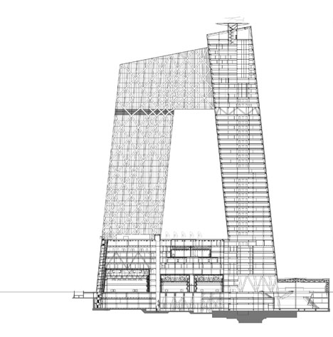
This highest tower stands 234 meters tall, with 54 floors and a 40x60mm footprint (2400m2) and a usable area of 405,000 m².
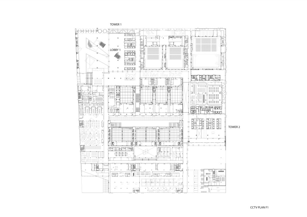
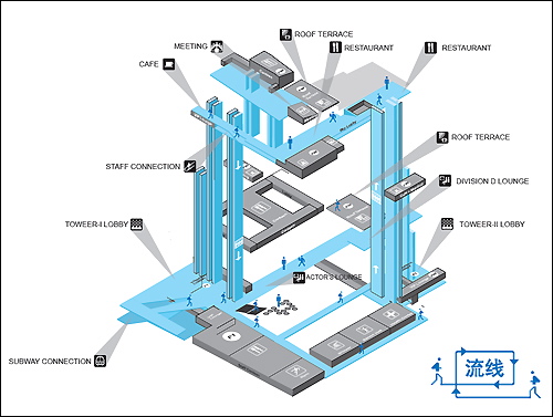
The main hall of Tower 1 is 10,000m2. It’s a six-story atrium that goes three floors underground and three more above ground level. It is also directly connected to the underground network of Beijing‘s subway system. This is where the10,000 workers who come to work to the CCTV headquarters everyday arrive and depart. The lobby connects to 12 studies which create TV; the largest study being 2,000 m2 .
The tower is divided into horizontal and vertical sections, which makes it look like a structure attached to land instead of just another skyscraper. This area will be used for the administration, news broadcasting, studios and production areas.
Tower 2
Tower 2 has a height of 210m divided in 44 floors, with a slightly smaller footprint of 40x52m, 2.000m2.
This tower houses the Cultural Center Television (CCTV ). It also includes a hotel, a visitor center, a large public theater with 1500 seats and exhibitions facilities.
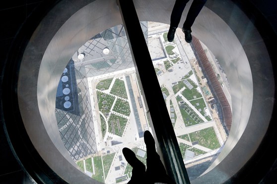
The CCTV headquarters allows a degree of public access to production facilities that is unprecedented in the Chinese media. An “Open Loop” takes visitors through the building, exposing the daily work of the studies and the history of CCTV, culminating with spectacular views of the financial district, the Forbidden City and the rest of Beijing from over the cantilever.
Structure
Seismic studies
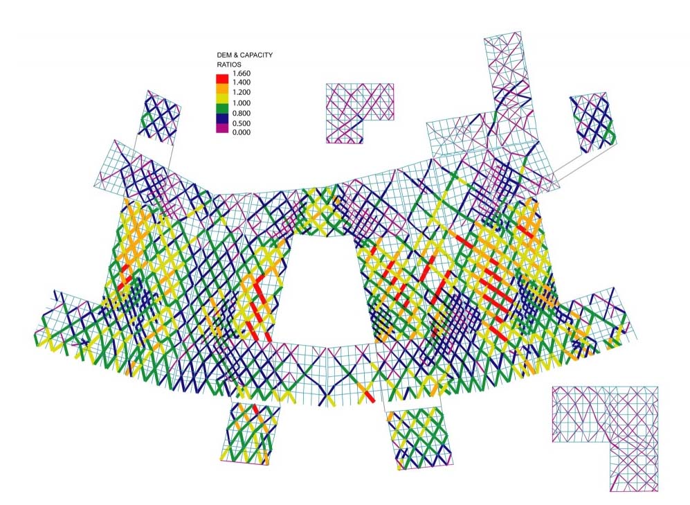
Because the seismic design of the CCTV building fell way outside of the scope of what Chinese regulations could evaluate, Arup proposed a design approach based on the technique, adopting basic principles and modern methods as guidelines to achieve set performance objectives at different levels of seismic events. Explicit and quantitative design checks were made using linear and nonlinear seismic analysis, allowing to verify compliance with the three levels of seismic design required by Chinese authorities.
Basic Quality Targets
- No structural damage when subjected to an earthquake of level 1 with an average return period of 50 years.
- Repair structural damage when subjected to an earthquake of level 2 with a return period of 475 years.
- Accepted severe structural damage without risk to collapse when the building is subjected to an earthquake of level 3, for an average return period of 2500 years.
In the location where CCTV was built, the values for horizontal ground acceleration during the three levels earthquakes are 7.20 and 40% of gravity’s acceleration. The structure posed a challenge for engineers because its two towers had to be supported at an angle 60°, to then bend 90° at its top and bottom, forming a continuous loop.
The towers were built in the opposite diagonal corners with a footprint of 160 x 160 meters, on a base of 45m in height and 9 floors, connected by a podium in a ‘L’. In its upper part were co- joined by a bridge to ‘L’ parallel to the podium. Thin concrete cores inside the building support internal floors. Basements with 4 levels reaching up to 18m below ground.
The construction of the two towers tarted in opposite corners of a 160 x 160 meters footprint, on top of a 9 floors, 45 meters high ‘L’ shaped podium. Once the two towers reached their final height they were connected by a similar ‘L’ shaped bridge. The upper part of the structure consists of concrete cores supporting the internal floors, while the 4 basements floors reach up to 18 meters below ground.
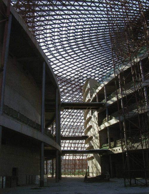
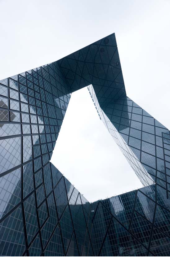
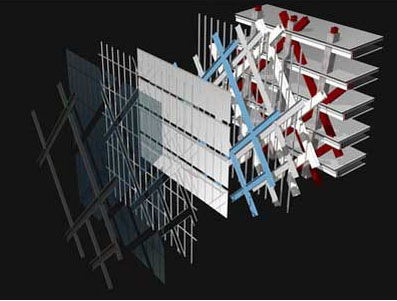
Exoskeleton
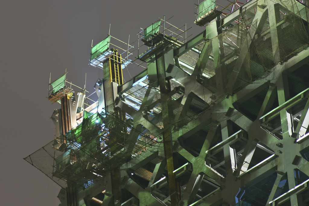
The exterior of the building has an exoskeleton system made up of diagonal grids in a loop structure that opposes gravity and any lateral force. The positioning of the columns and downtubes reflects how forces are distributed across the surface skin of the building. All exposed parts of the diagonal column grids have the same width, but their depths vary according to how much load they’re bearing. Meanwhile, all diagonals are 1m x 60 cm plate girders, which only change in the thickness of the steel.
The building breaks Chinese design codes for such structures, but the system was accepted for being an innovative design that would become an icon of the 2008 Olympics and beyond.
Facade
The headquarters of CCTV’s façade is a manifestation of the structure and forces at work within it. A network of diagonal lines becomes dense in areas under greater stress, while more flexible and open areas require less support. The hybrid freestanding facade features glass panels with a high performance sunscreen that creates a subtle silvery gray color, giving the building an unexpectedly muted presence on Beijing‘s skyline.
Elastic design
Once the engineers determined the initial pattern of reinforcement, they put all load combinations through a series of elastic linear checks using a modal response spectrum.
Engineers tested every element in the building and verified its performance. They also put the selected items through an earthquake level 2 test for elastic analysis to make sure key elements like columns could withstand it.
To validate the response spectrum for Level 1, engineers looked at historical data from past seismic events.
Foundations
The design of the foundations required that the loads applied to superstructure were redistributed through a “pilecap” raft in order to guaranty that all pillars received enough weight to provide adequate strength and stiffness. In order to validate spread load per pillar groups, engineers used a complex iterative process of analysis which adopted a nonlinear soil model.
The loads to the superstructure were calculated by sections. Several hundred automated directional charges were altered in a spreadsheet for GSRaft control software to analyze soil-structure interaction nonlinearly. This procedure changed the input data according to the test results to repeatedly model how charge is redistributed between piles when their safe working load limit is reached. The analysis was repeated countless times until the results yielded sections that were all within an allowable capacity. The data from these hundreds of analyses was then used to design reinforcement for the raft itself.
Connections
The goal is to have the force from the braces and edge beams go through the column with as little disruption as possible to pre-existing tensions. To do this, engineers replace the flanges with a steel “butterfly” that goes through the face of the column. This is then attached to clips and edge beams.
In order to make it easier to construct concrete around this steel section, no network connection was attempted..
As a “strong joint / weak component,” seals must work with braces, beams and columns. Clamps deliver probable maximum loads to connections, which must be able to withstand these loads while still performing well and minimizing stress concentration. However, high levels of stress can break delicate welds during earthquakes, something that was seen often after the 1994 Northridge earthquake in Los Angeles.
The team created models of the connections, both typical and more severe, in AutoCAD drawings. Then they used MSC/NASTRAN to subject them to different levels of force until they broke or buckled. This let them to see how much stress the joints could take without failing and identify where stress would be most concentrated.
Lastly, the butterfly shape plate was adapted to soften the corners and notches until potential regions of weak performance were minimized. This allowed for a greater concentration of efforts at normal levels, which is common practice in civil and mechanical engineering.
Videos