Dubai Metro

Introduction
The city of Dubai picked, in 2005, the company Aedas to perform the proposed metro line in the city, the first system of this kind in the UAE. The company, also responsible for the Torres Al Bahar to Abu Dhabi, launched its teams numerous architectural projects, design and structures station auxiliaries were conducted in Singapore, the design of the tanks fell Aedas Aedas Birmingham and London on 3D computer modeling support.
The design and construction of the entire system, including trains and railway systems, has been assumed by the consortium of Mitsubishi Durl JT Metro JV:-Obayashi-Kajima-Yapi Merkezi.
Planning
Planning the Dubai Metro began under the directive of the Emirate’s ruler, Sheikh Mohammed bin Rashid Al Maktoum. Based on initial studies, begun in 1997, the Municipality of Dubai emphasized the need for a rail system that would provide additional capacity and relieve growing motor traffic congestion, supporting the continuation of urban development.
In May 2005 approved a design submitted by AEDA, the contract being awarded to Dubai Rail Link [Durl] consortium of Japanese companies, including Mitsubishi Heavy Industries, Mitsubishi Corporation, Obayashi Corporation, Kajima Corporation and the Turkish company Yapi Merkezi
Location
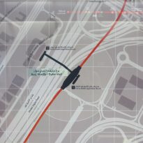
The project consists of 52 km in length to the Red Line running from Rashidiya to Jebel Ali port, through the area where the highest concentration of strange skyscrapers of New Dubai.
The 22 km long Green Line extending from the Ciudad Sanitaria (Health Care City) to Airport Free Zone of the city of Dubai, Arab Emirates.
Concept
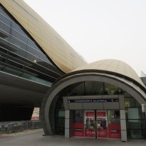
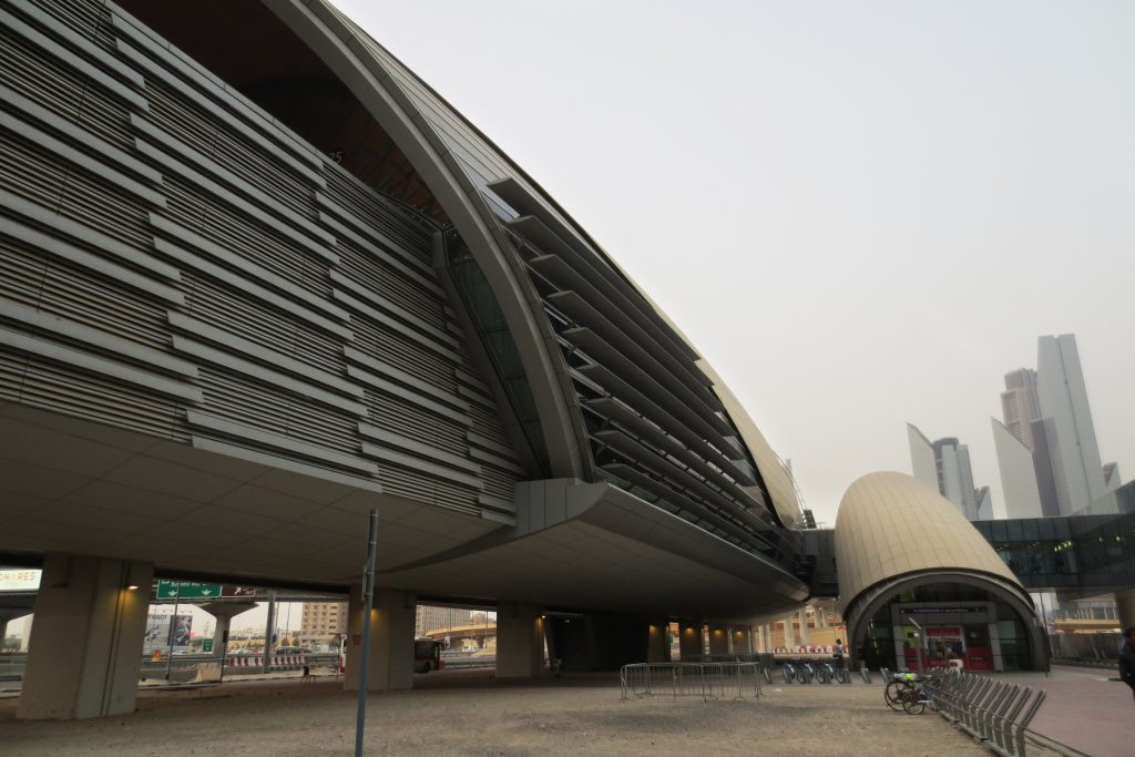
The design concepts of the stations respond to explicit Dubai Municipality requirement for unique designs, innovative, iconic and symbolic.
Design

At the beginning of the sketches were proposed stations were modeled on the wings of a hawk or stations that were modeled optical fiber cable.
Mr Agoston, group director of design comments:… “You start playing with a piece of paper playing and turns around, and you’re thinking, it’s fun,” he said. “Beyond that, you have tons, literally tons, paper before reaching the final drawings. Not many people see that. Sometimes they say, “You only have 56 drawings?”
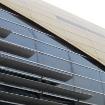
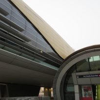
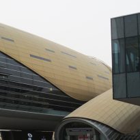
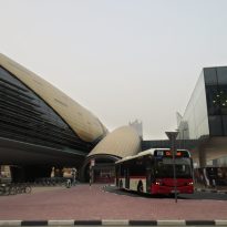
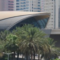
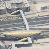
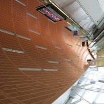
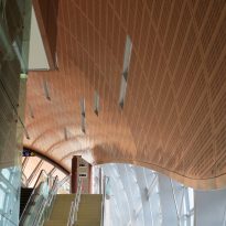
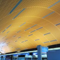
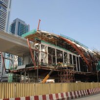
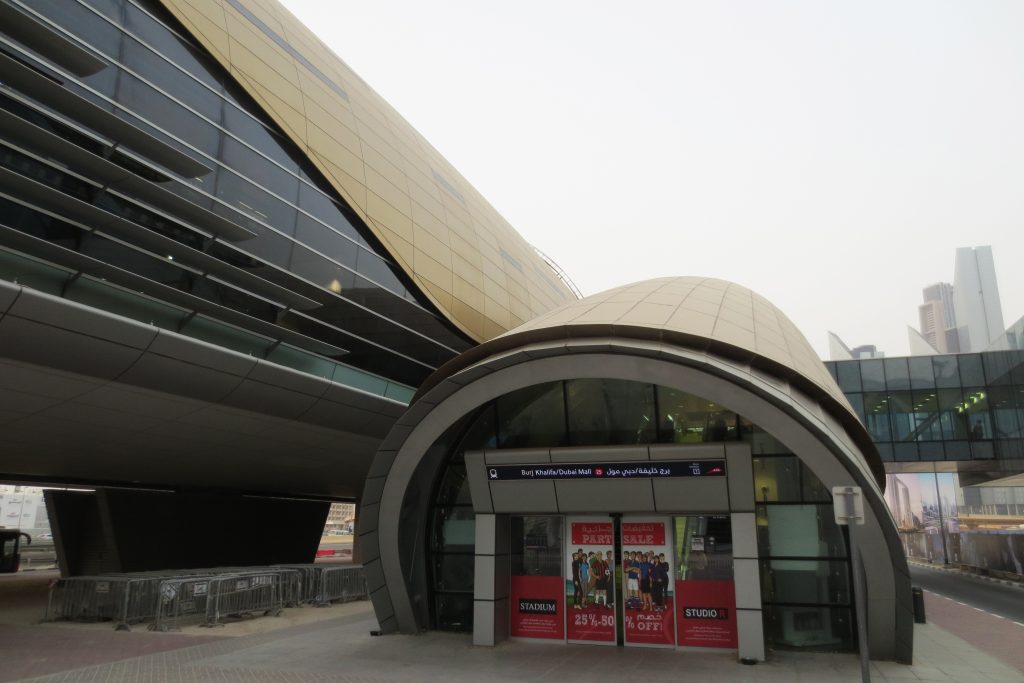
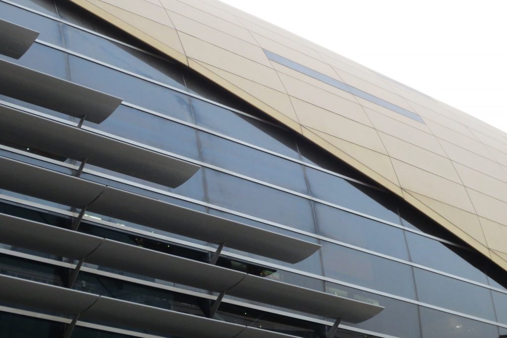
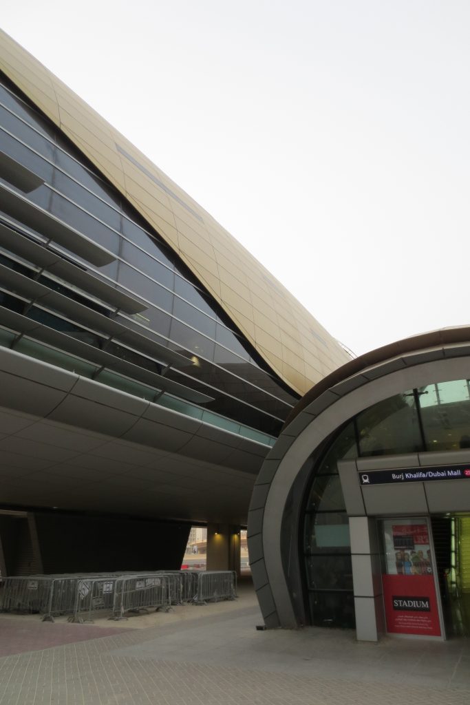
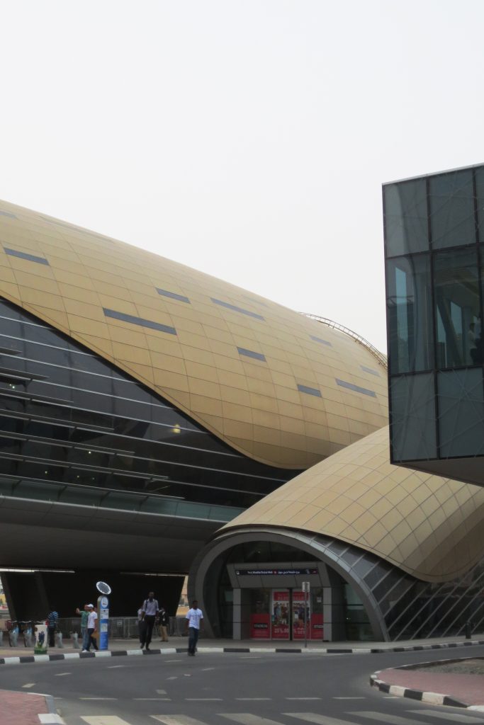
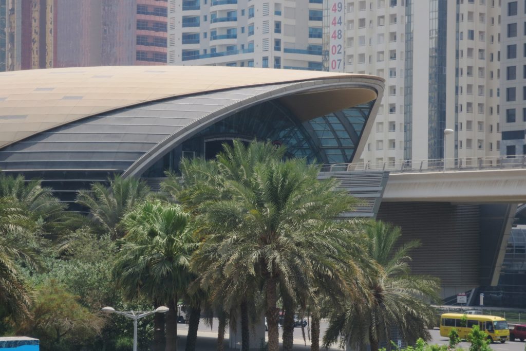
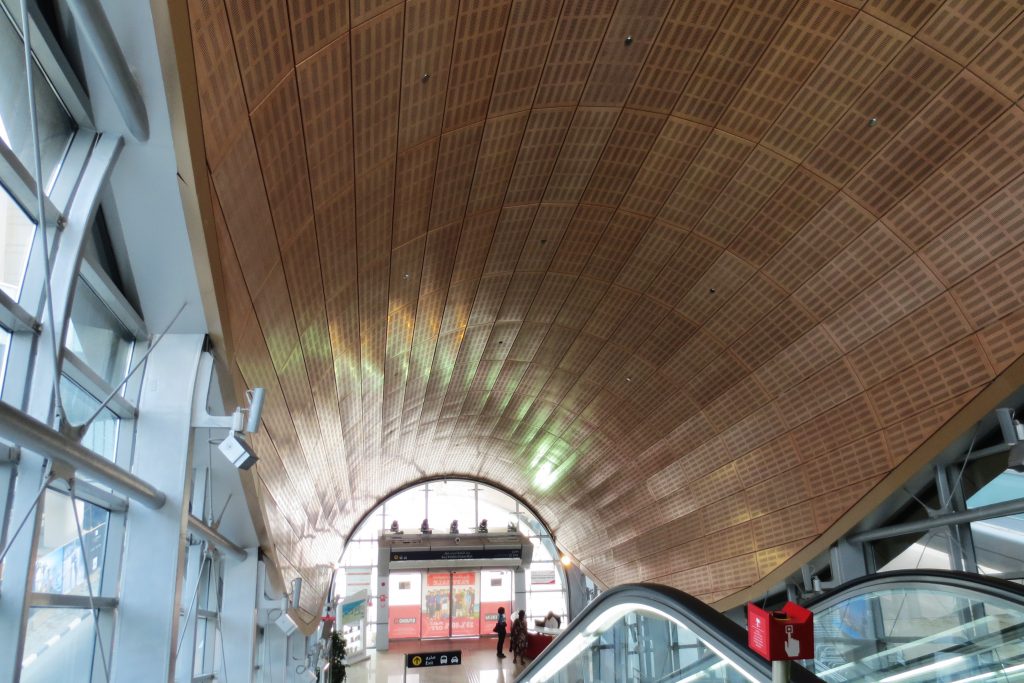
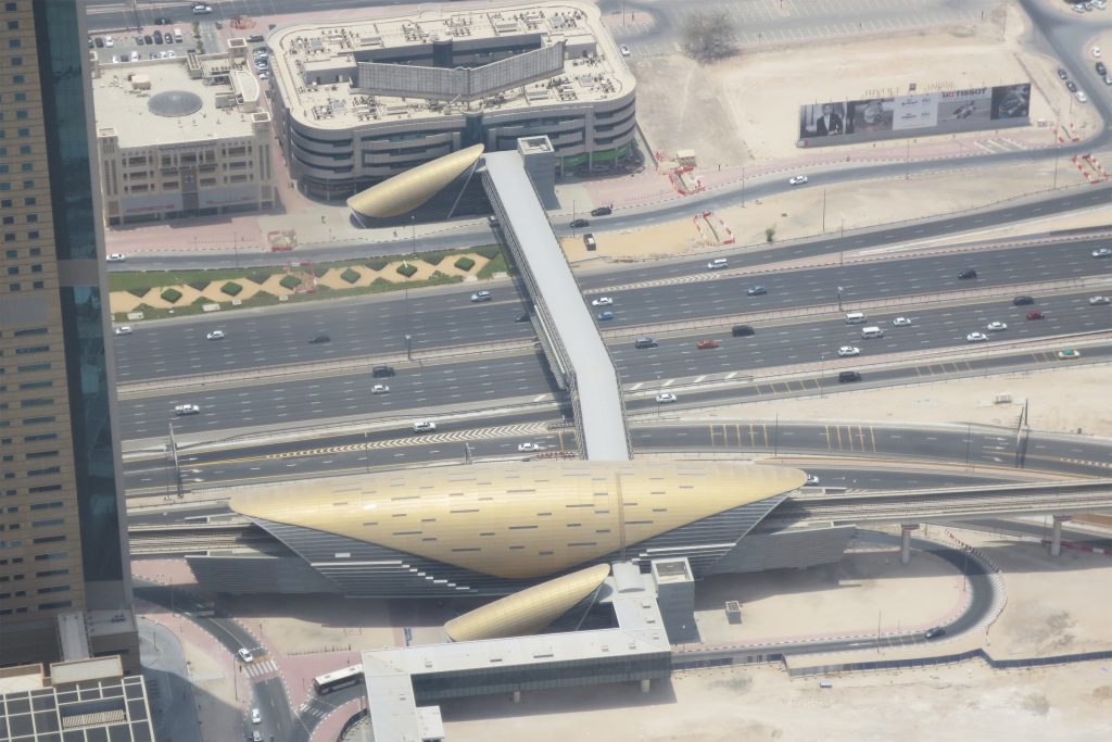
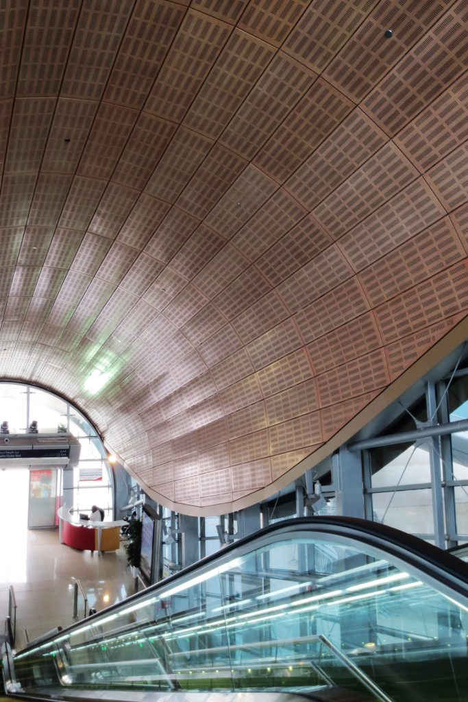
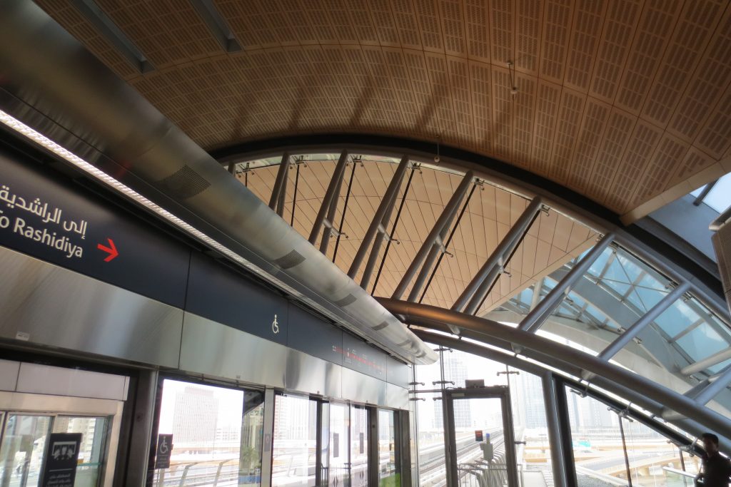
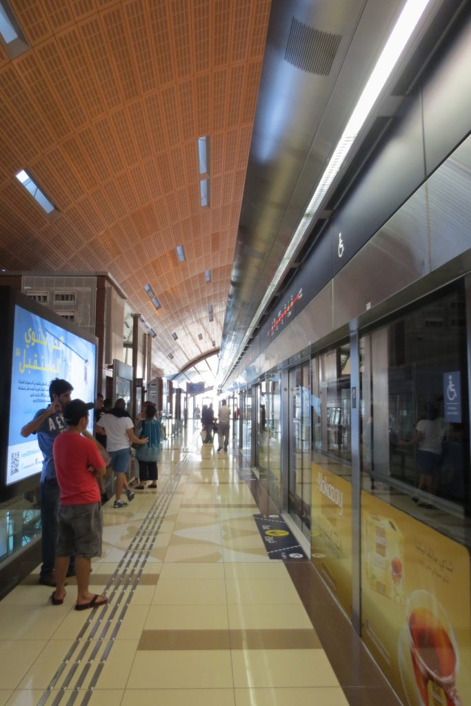
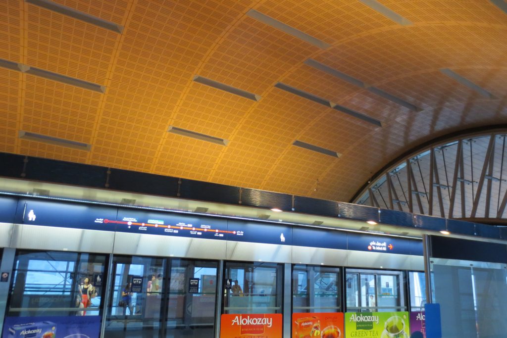
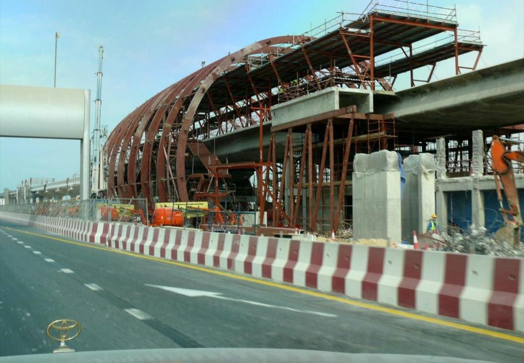
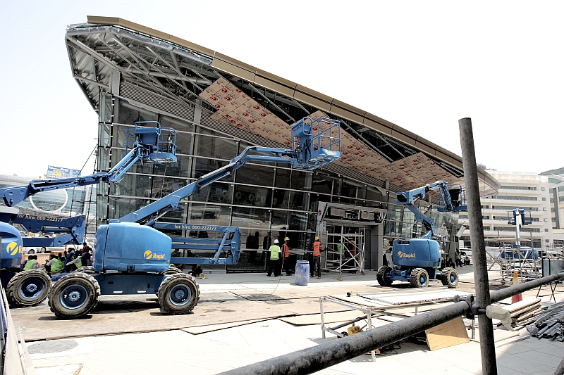
After four years, these drawings have become material interlocking concrete slabs and steel columns. And not only did the simple design for the gold and black stations allowing quick assembly, but the symbolism of inclined facades, ultramodern, remain true to the heritage of the UAE.
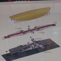
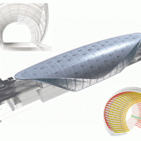
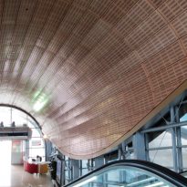
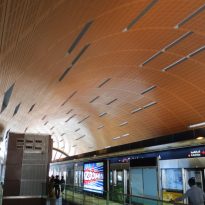
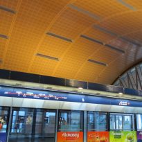
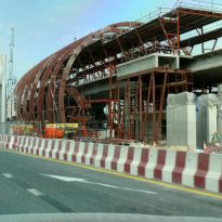
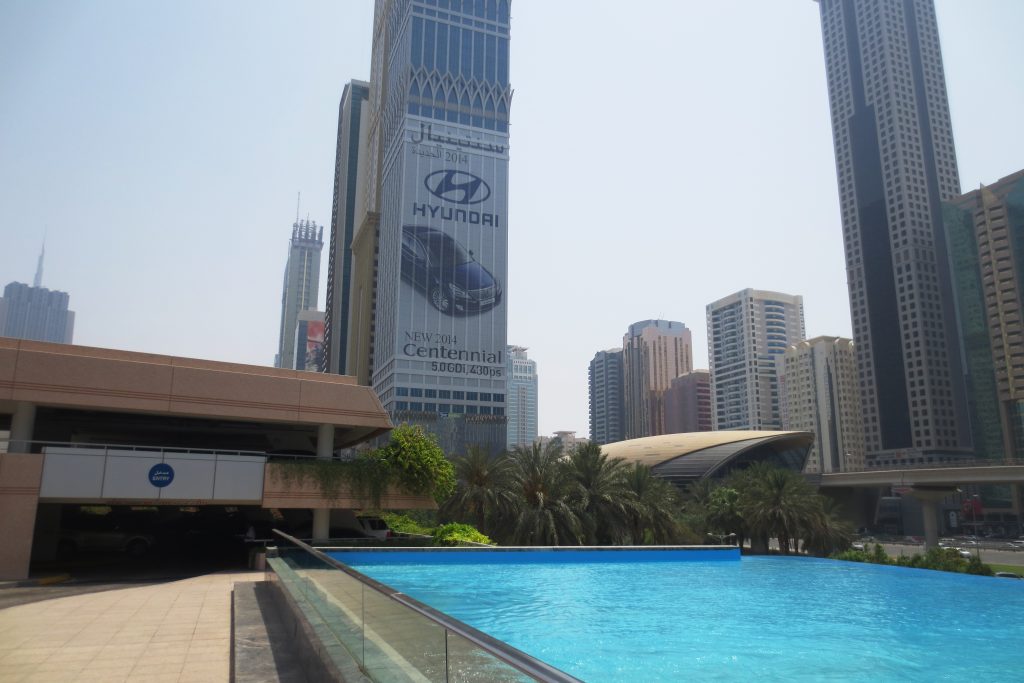
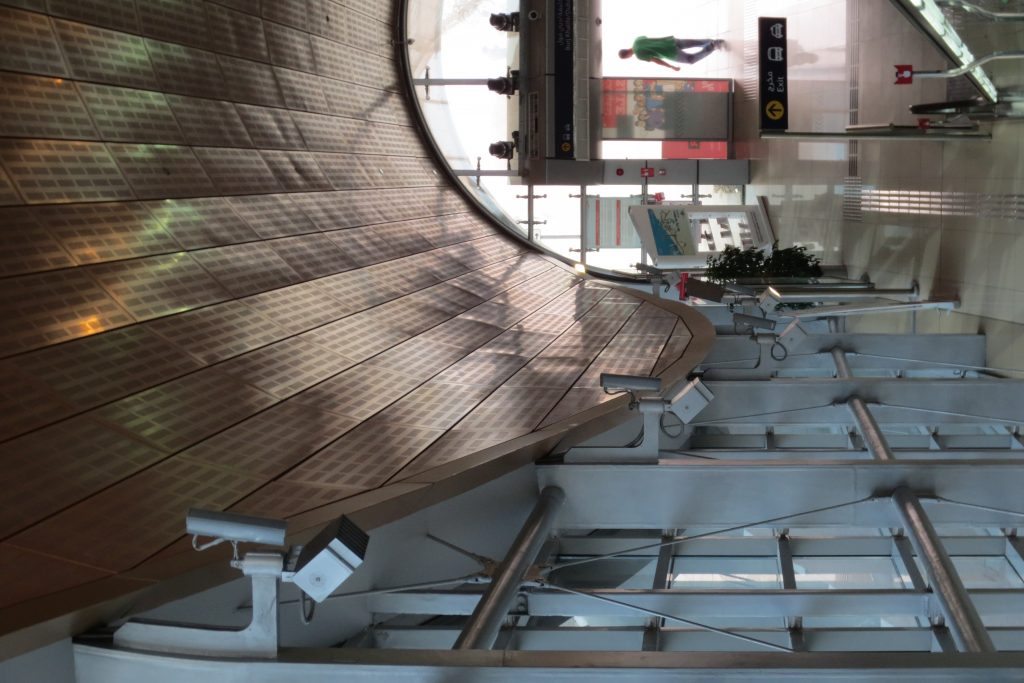
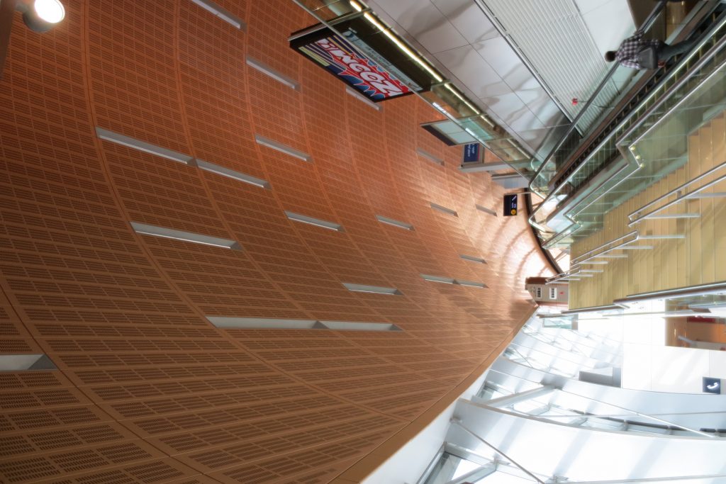
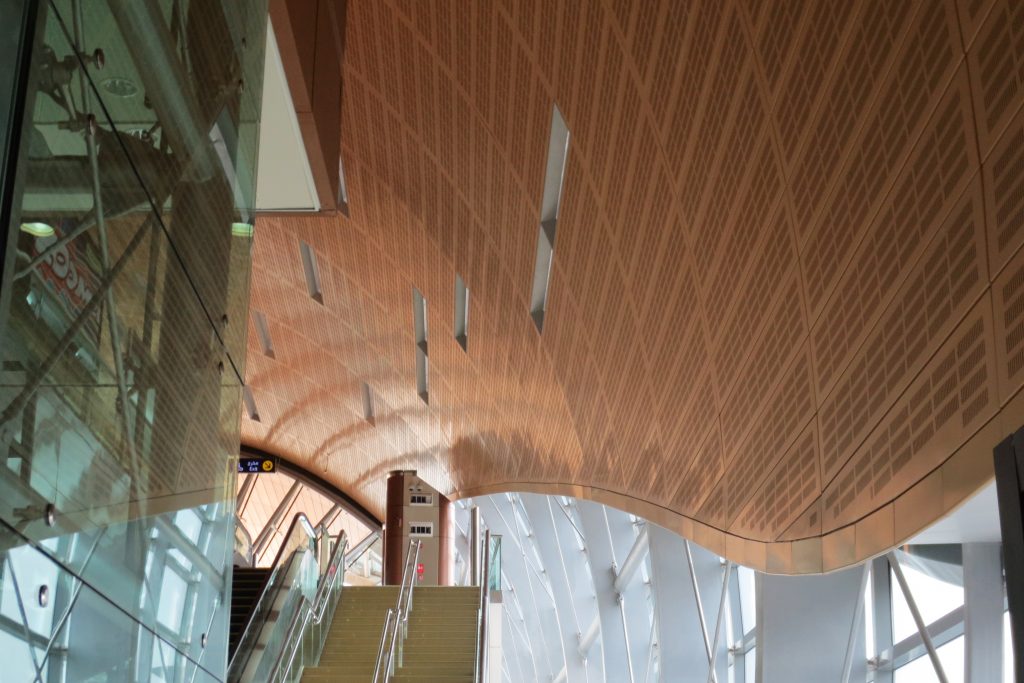
The concept behind the design metaphor is based on the pearl, delicate object that was once a staple of the economy of the Emirate. “We had to make these stations are relevant”. Metro stations have a unique design, combining modernity and tradition. Her decks, with a unique shell shape, although modern diving heritage invoked to find pearls, ancient art that requires skill and courage and prosperity brought an early becoming an integral part of the history of Dubai.
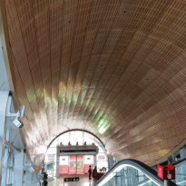
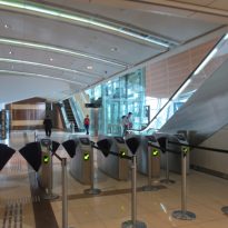
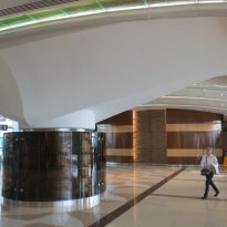
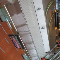
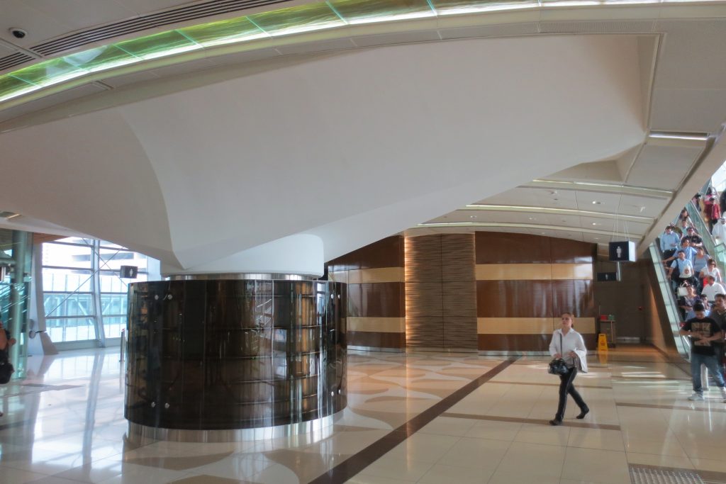
The interiors of the stations have a design, also unique, in relation to its historical background and adopting a design theme based on one of the four elements of nature: water, air, fire or earth.
Spaces
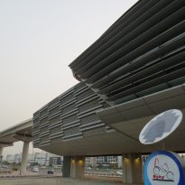
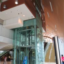
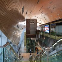
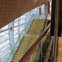
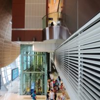
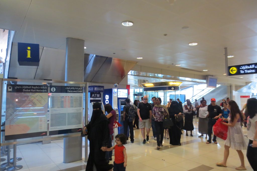
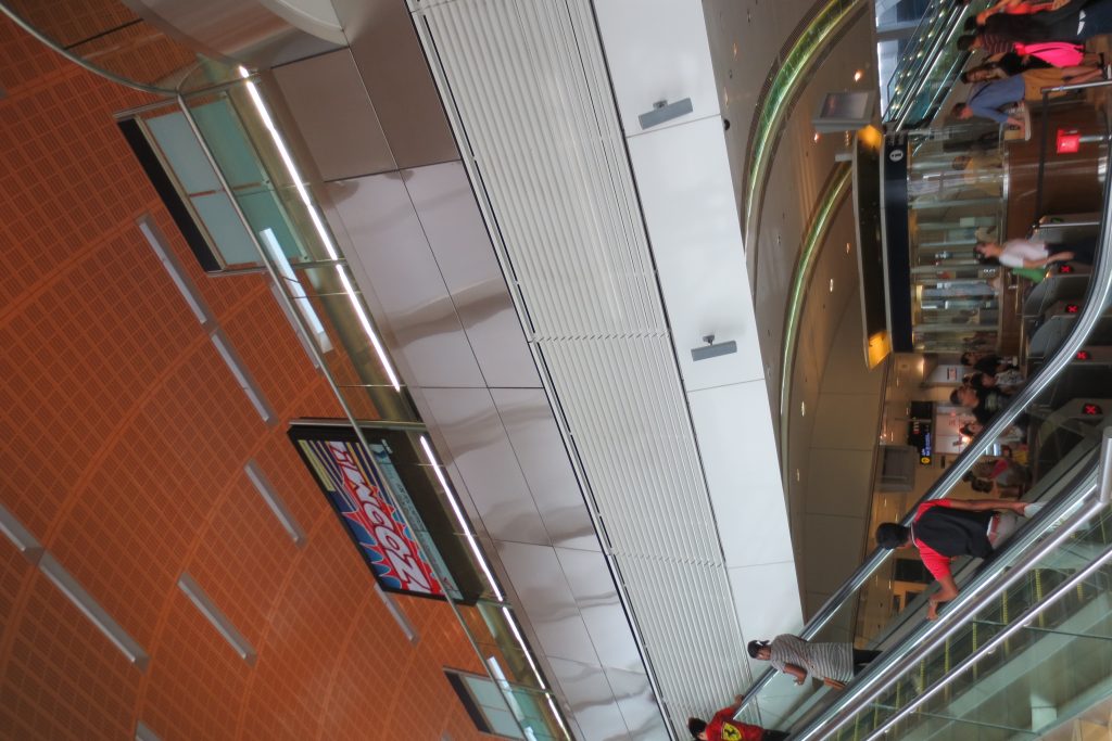
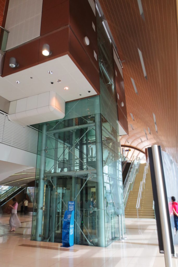
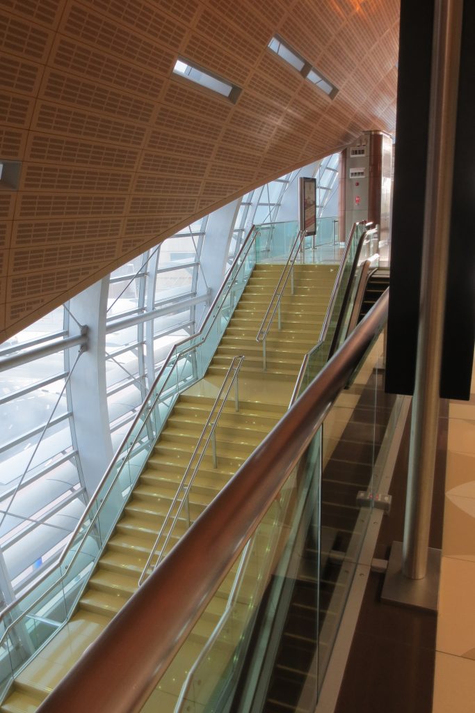
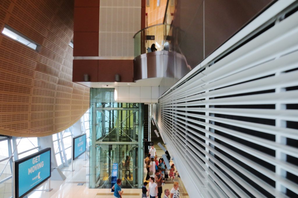
The 52 and 24 km from the red and green line along traverse 47 Dubai Metro stations, some of which are at street level, others that are most high, and ten are underground. A total of 205 bridges with steel trusses provide 24-hour access. Air conditioning is available for the general public to enter the elevated stations and these allow the crossing of variety of ways along the route.
Types stations
There are four types of Metro stations
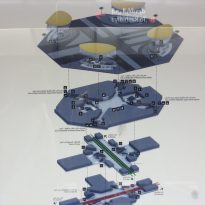
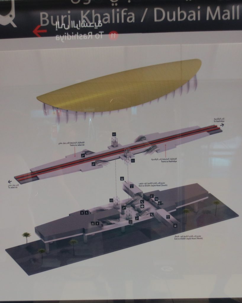
Type 1: elevated station, 3 levels, street-level lobby, mezzanine mechanical rooms, two side platforms on level 3. Surface area: about 1.800m2. An example of this type of station Emirates Tower Station.
Type 2: elevated station, 2 levels, lobby at level 2, two side platforms, approx 1.600m2. An example of this type of station Mall of Emirates Station.
Type 3: Elevated Station 3 levels, with ground-level lobby, mezzanine plant room, two side platforms on level 3 and unlike the other station 3 levels, this provides an extra line for parking and repair station. Its surface 1.900m2 Nakheel Station being one example.
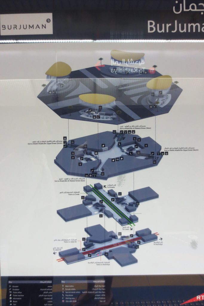
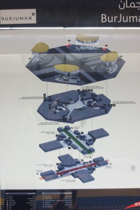
Type 4: Typical underground metro stations, with the lobby on the first basement, basement intermediate engine room, two side platforms on level -3. An example of the link between Union Station and BurJjuman Square.
Another variety of these underground stations have the lobby on level -1, an intermediate level for engine room, two levels of side platforms at the -3 (green line), two-level side platforms -4 level (red line), parking and connections.
Most stations have limited parking, the largest being those at stations Rashidiya and Jumeirah Islands, along the Red Line, as well as Al Qusais Station on the Green Line. Each metro station has a bus stop and taxis.
Construction
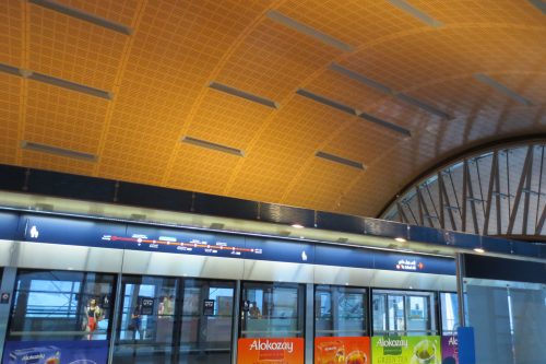
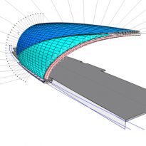
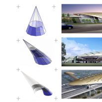
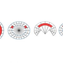
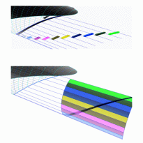
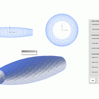
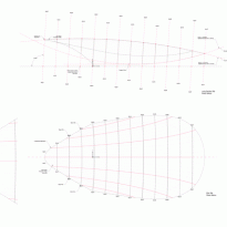
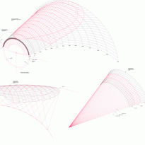
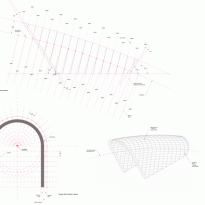
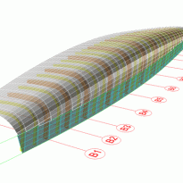
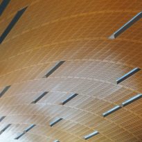
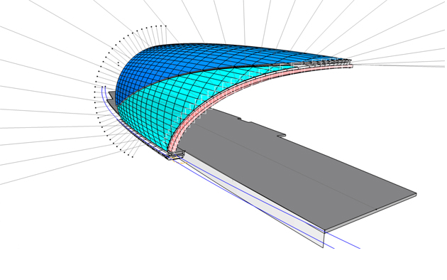
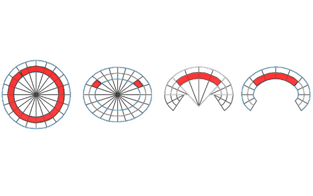
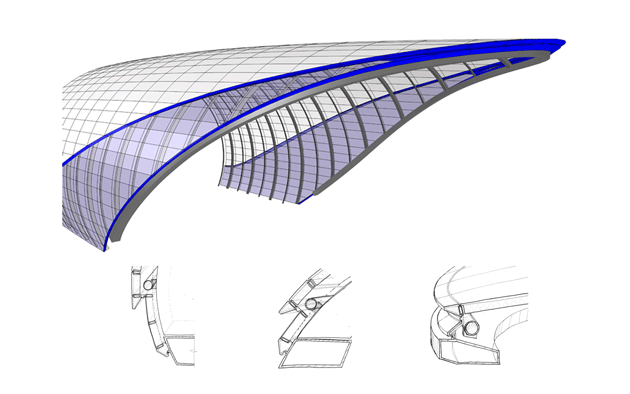
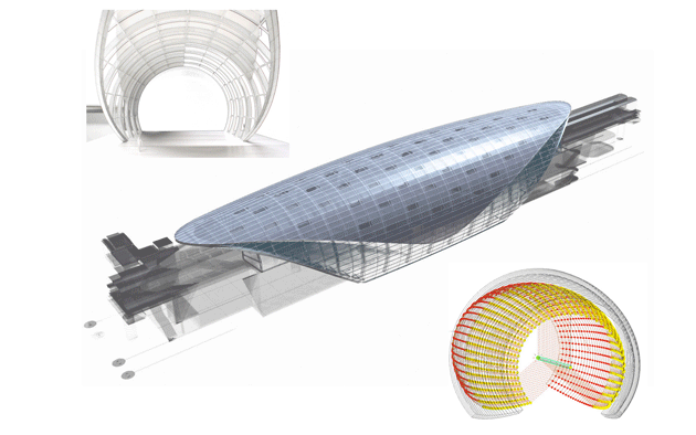
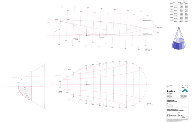
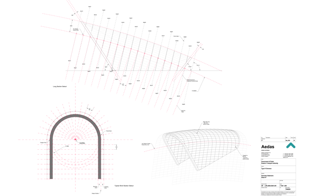
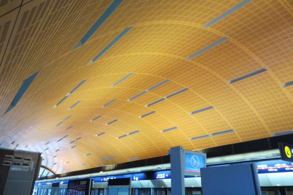
By controlling the geometry in the form of the building, the equipment is capable of managing complex factors along with the design concept to facilitate improved quality of execution. The result allows us to consider and anticipate the complexities of the construction process. Advanced Modelling Group, Advanced Modeling Group, uses a number of software packages as needed to control the geometry and extract relevant data, such as panel schedules, deviation, and others. Specifically to the materiality and intent of the design, control building geometry can include pre-rationalized conical arches or slots based geometric surfaces.
- Phases
Phase I – Red Line
The red line has 25 stations off the ground, 4 underground stations, including two interchange stations and 2 rail yards. This line was completed in 2009.
Phase II – Green Line
The green line has 12 elevated stations and 8 underground stations. This phase was completed in 2010.
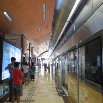
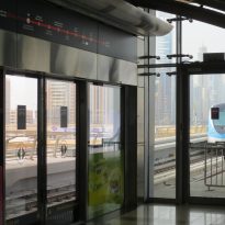
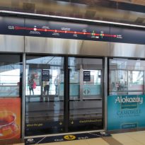
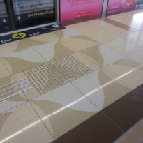
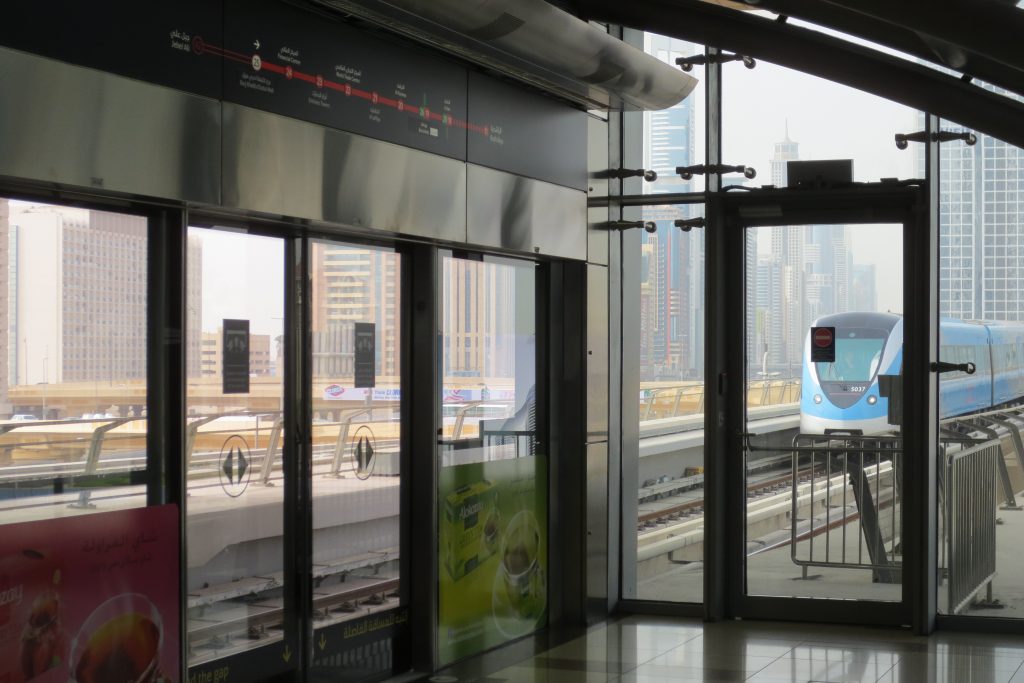
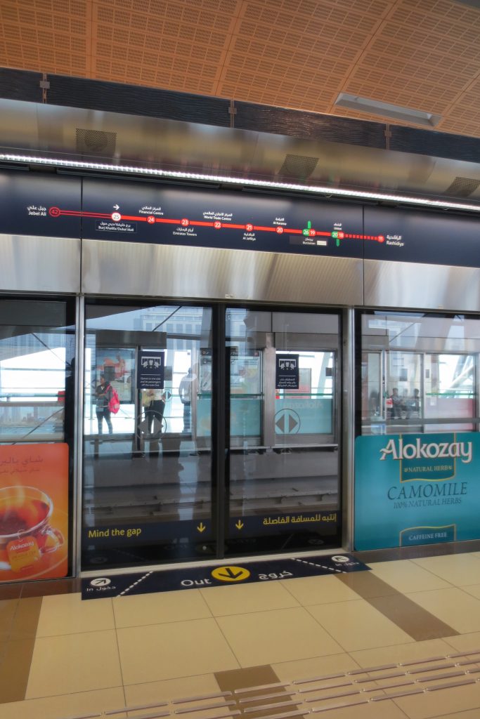
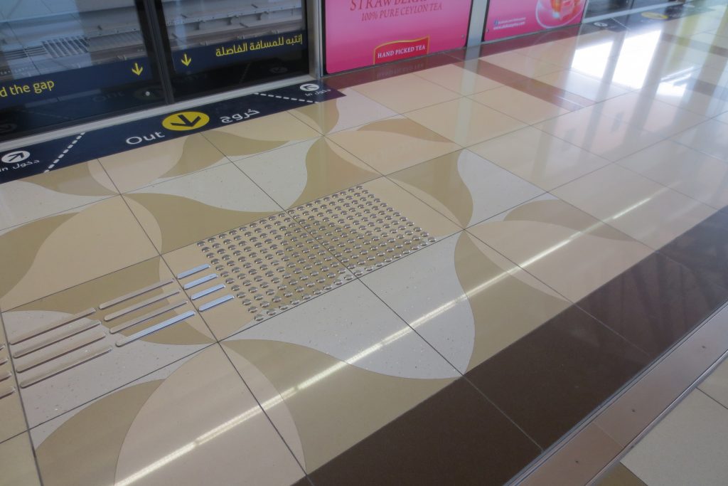
The fully automated metro system, has added a third rail that provides power if they fail the other two tracks. Screen doors and exit access to the cars are located on the edge of the platform, marked on the floor with signs for the blind, allowing better use of air conditioning in the platforms.
In all seasons four decorative themes are repeated:
- Earth with warm brown tones
- Water with blue and white colors
- Fire in orange and red colors
- Air with a pattern of green tones
Central Stations central
- -Deposit Al Rashidiya Station
The Red Line of Dubai Metro has two power stations, one in Al Rashidiya and Jebel Ali second.
Each “deposit” has a control center to operate trains and station systems, in addition to checking individual train system and security stations systems such as air conditioning, security, sound system and sophisticated electronic subsystems. It also includes workshops for carrying out maintenance and other workshops for washing and cleaning of trains.
Al Rashidiya Station has parking spaces for rail, air conditioned room for 64 units.
The choice of Al Rashidiya as one of the deposits was made for several reasons, among them that is in one of the end points of the route underground, its strategic location on the Emirates Road, near the Green Line as the unimpeded only place in the neighborhood.
- Jebel Ali Station-tank
The deposit from Jebel Ali Depot has an area of 110,000 m2.
Includes parking for train cars with air conditioning and is equipped with advanced fire-fighting system. It has a capacity for 40 trains.
Structure
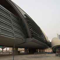
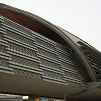
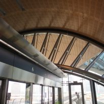
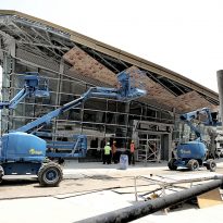
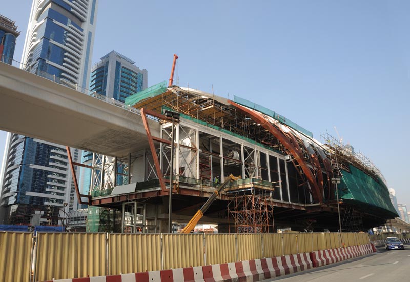
Aedas in the UK in collaboration with Aedas Hong Kong, Singapore and Dubai were in charge of the design of 43 subway stations and buildings associated with the tank in Dubai, with phase one completed in 2009. The landmark set of stations, developed by the Advanced Medelado Group consists Aedas conical shells with large overhangs that rise to more than 30 meters. The 3D geometric approach not only helped create an impressive way, but also allows a considerable saving of time and material efficient through interdisciplinary coordination leading to a substantial reduction in costs, time and energy.
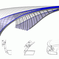
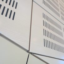
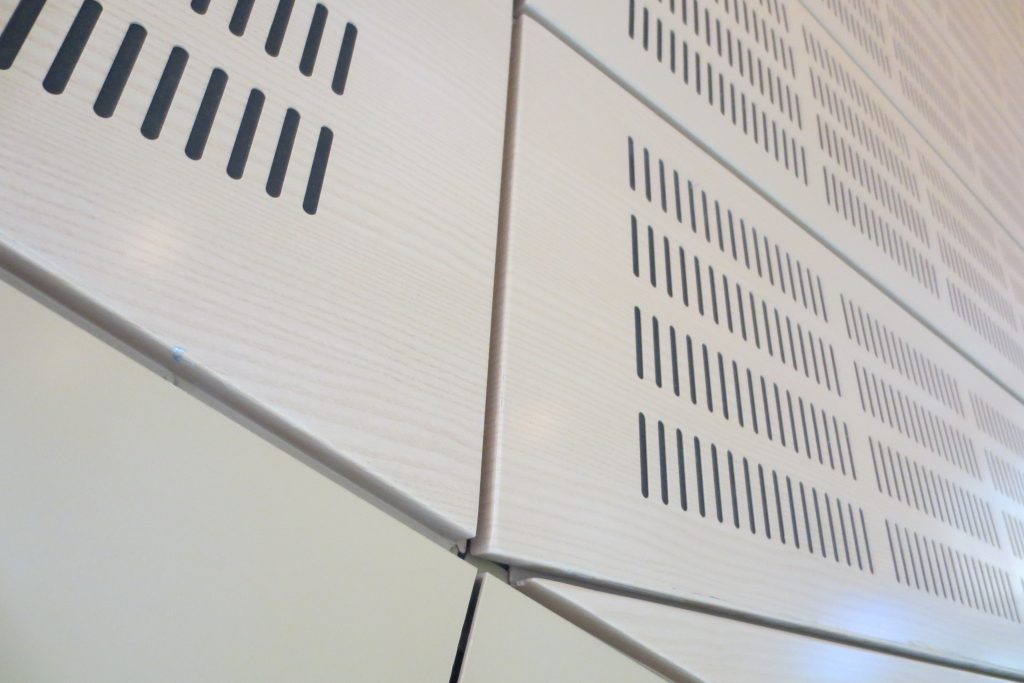
The group also provided details of the flash design interface between the cladding panels and structural ribs inclined. Built digitally, these details had to be designed within the tolerances allowed braided aluminum panels to attach continuous geometric changes.
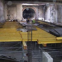
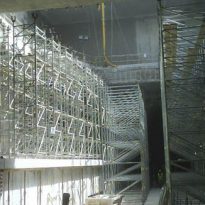
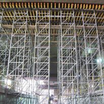
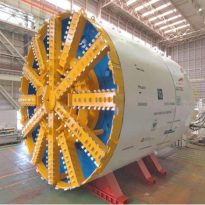
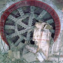
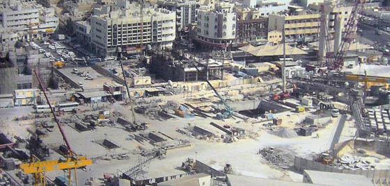
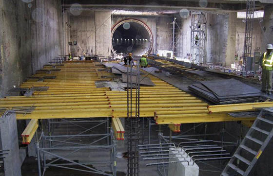
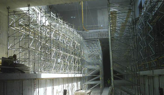
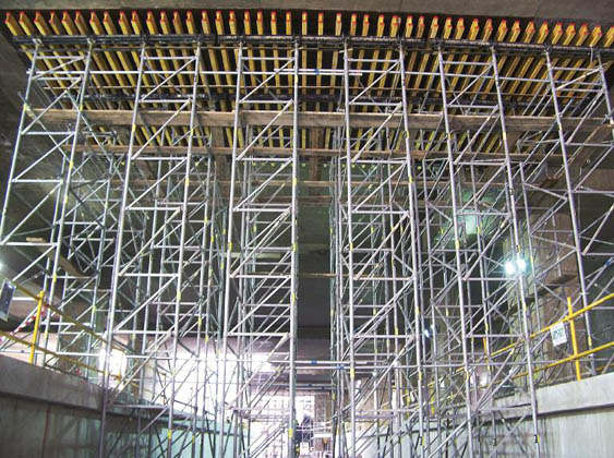
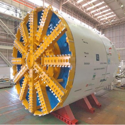
With ENKOFLEX Horizontal Formwork, consisting of standard parts, were run profitably concrete slabs up to 1.6 m thick. As an independent beam formwork, versatility allowed to adjust adequately to irregulares.La slab load transfer to a height of 12 m between slabs was performed with shoring towers T-60 along with Struts EP. The shoring towers, fast and simple assembly, facilitated their transfer from one location to another, as it was not necessary to disassemble them for use in the next time. For underground construction, 10 km, both the red line to the green, we used three TBMs, TBM.
Walkways
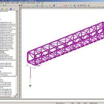
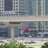
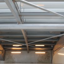
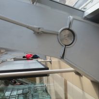
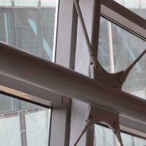
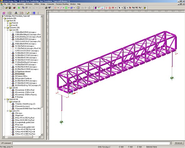
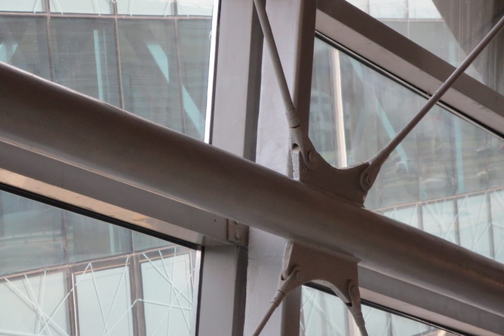
The engineering firm Atkins has used the analysis software to LUSAS Bridges that helped in the analysis and design of a large number of bridges with steel lattice, used to facilitate pedestrian access to the elevated stations of the project and to allow crossing roads along metro route.
Bridge LUSAS using program analyzed the greater length of each of the major types of bridge. For each gateway, 3D elements for thick beams molded main structural elements of steel frame, cross braces, as well as the head of concrete piers and docks them. Support piles were modeled using the equivalent cantilever method. Common elements represent stiffness and adequate freedom of articulation bearings.
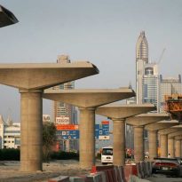
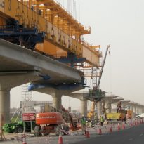
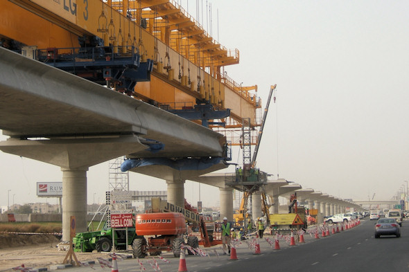
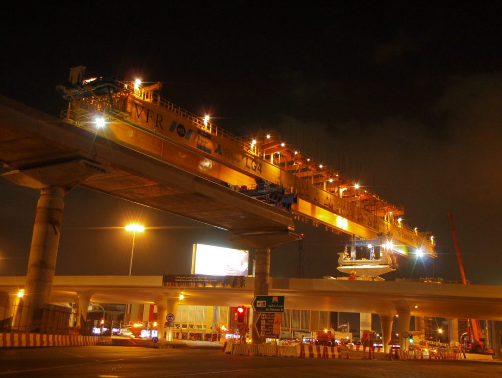
By LUSAS software engineers analyzed various project structures, including seismic analysis of the substructures of the viaducts, which were derived peak bending moments for use and design, reinforcing the pier and pillar sections. The viaducts of the Red and Green Lines are constructed with a combination of elements in some cases and in others with a single length of countertops with post-tensioned shaped cross section U supported on elastomeric bearings, and two or three openings continuous platform supported on beams fixed or sliding.
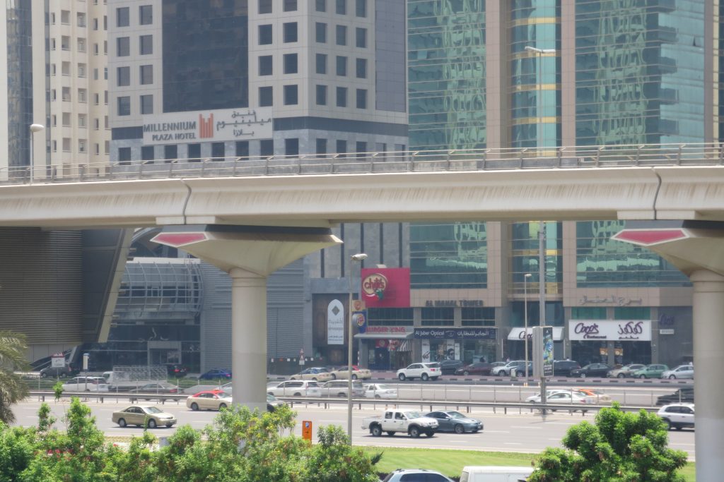
Most of the viaduct sections are 28, 32 or 36 meters in length and are supported by individual columns circular concrete of 1.75 m or 2 m in diameter. Morros flared pillow cover. Because of the speed that it was necessary to keep the construction simple springs are supported by pillars of 2.0 or 2.4m in diameter. In individual sections, double and are prefabricated stations, but require the filling of concrete and prestressing is performed in situ. The viaducts hills for three continuous spans structures were built all in situ, using large diameter pillars.
- Seismic analysis
Most deck sections are mounted with fixed frames, but due to the design of the platforms and piers, temporary loading construction of the frames is less expensive than any potential caused by seismic loading. To analyze the dynamic behavior of structures numerous two-and three-span viaduct in continuous 3D models were developed from initial 2D cross model, using a very similar modeling methodology.
To account for the effects of twisting of the cover have been using thick shell elements. While the cover profile varies in thickness along its length, for the purposes of modeling the calculated average thickness for each of the variations of density and mass of the deck along the span, used to ensure that variations mass was properly distributed platforms for seismic evaluation. Simple supports three on each side of the continuous structure of two or three openings were included in each model to reduce border effects.
- Spreadsheets
Based on the formulas and design methods specified in UIC code 774-3, Atkins spreadsheet used to assess the interaction effects in the structure of the railway for 1200 spans extending on both lines, the red and green. While based on the UIC code simplified techniques, which generally produce conservative results, this approach had the advantage of allowing a large number of openings arranged in relatively quickly evaluated.
Rachel Jones, engineer on the project, said: “For verification modeling LUSAS chose a selection of arrangements in some vain, with which we would get a variety of effects or simple combinations of 2 and 3 bays on stretches of continuous decks. Tensions in the lanes obtained by the analysis showed that the spreadsheets were being properly ”
- Modeling with LUSAS
To verify the results obtained from spreadsheets LUSAS Atkins used the program to model and analyze a set of representative arrangements. The models are built with thick beam elements to represent the piles, piers, concrete sleepers and covers. Pillars modeling was performed using the equivalent cantilever method (in comparison with the modeling of the interaction soil / structure as a beam of elastic springs). Common elements of adequate stiffness and shape required places elastomer and other support. Thick beam element only offset by a corresponding eccentricity represents cover the two sets of rails. Nonlinear common elements fasteners shape of the track. Thermal load cases were applied to the elements that represent the cover according to UIC code 774-3. Freight train both vertical live load and horizontal braking loads are applied to the elements that represent the lanes in places of interest in the model.
Materials
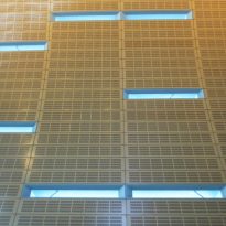
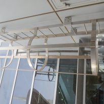
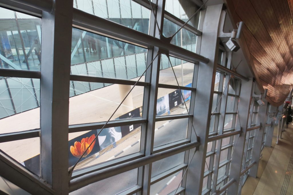
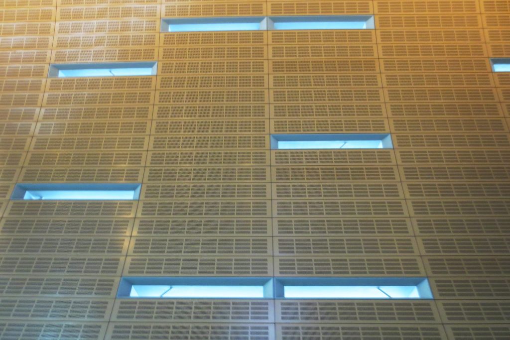
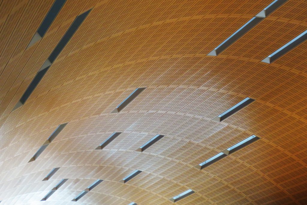
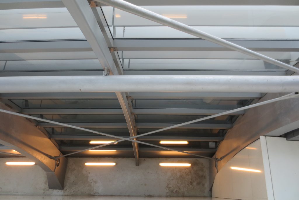
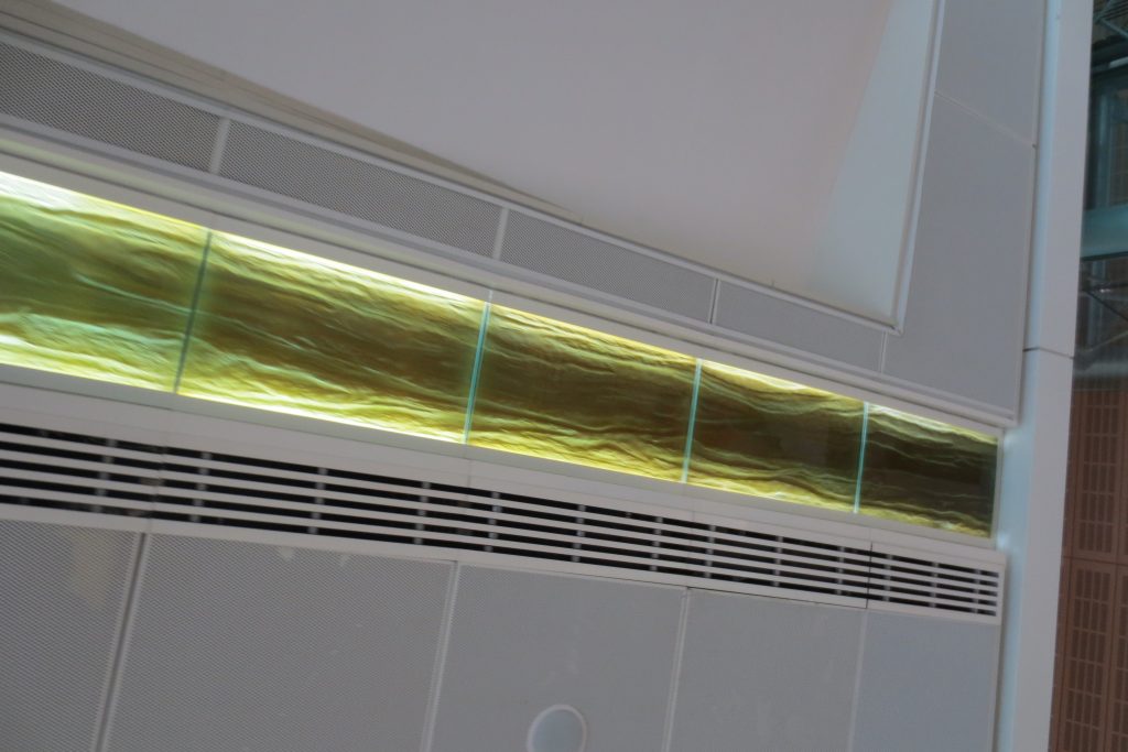
KCA International, a British firm hired by Aedas for interior design, chose a colorful style ornament for the stations of the red and green line that is meant to symbolize the natural elements of earth, water, air and fire. Everything from ventilation and natural light getting in the subway stations, the shape of the glass from the outside to the surface stations, had to be carefully analyzed and modified seemingly countless times.
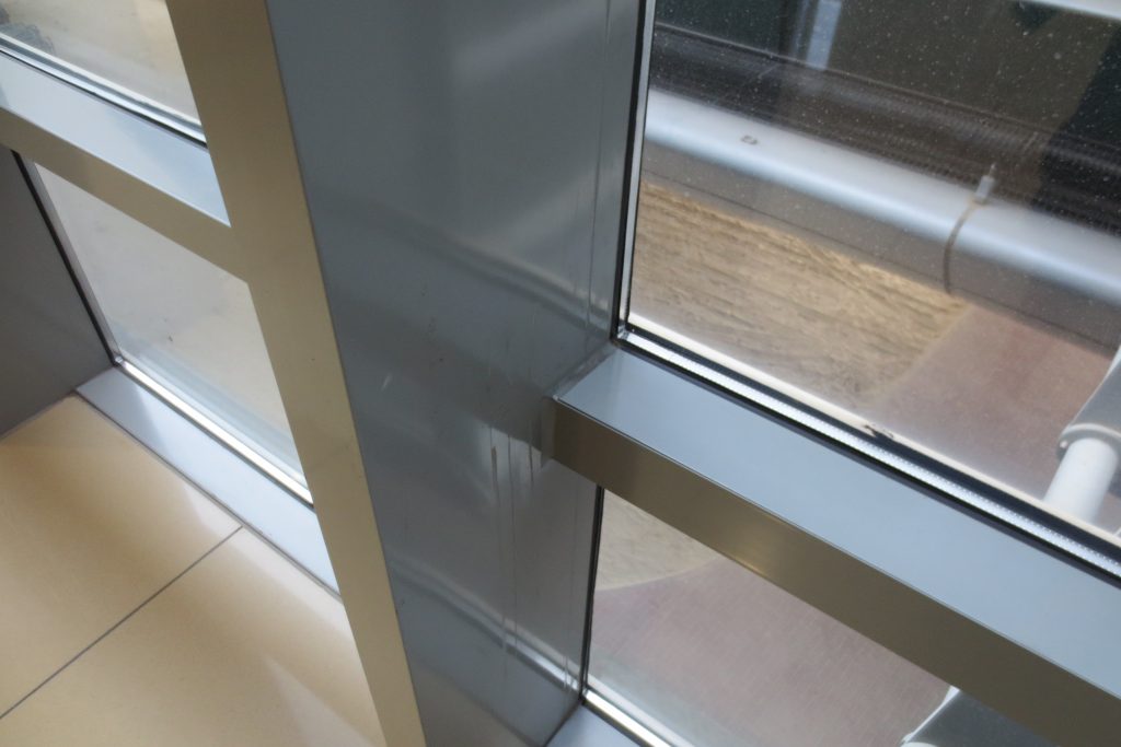
“To design something of this magnitude, you need a standard panel, without too many ways to make it easy to build Mr. Troup said outer glass of the seasons.” It’s very rational, pure geometry by computer. ”
Sometimes, participating in a project with a unique hierarchical structure of consultants and engineers requires commitment. In some projects, the differences of colors and shapes have to be put aside, as with the 19 pedestrian bridges, designed by another company involved. Regardless of minor aesthetic differences, Messrs. Troup Agoston and together with his team of designers feel, once the project is finished, as if they had left their architectural mark in a little history.
Walkways
For decks, platforms and key components of the substructure is used precast concrete.
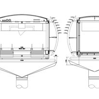
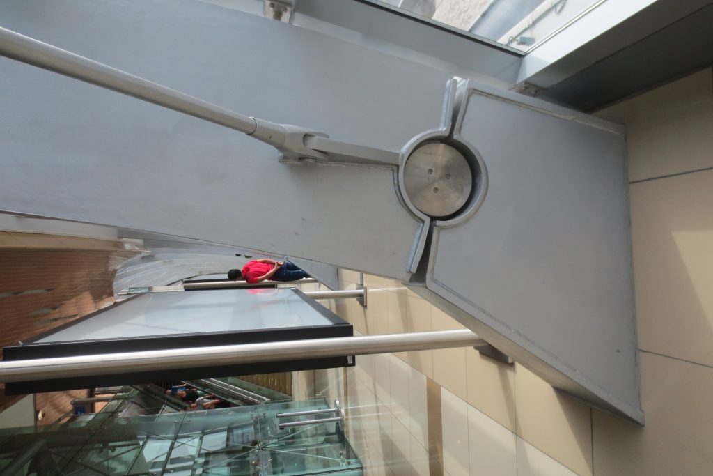
Before installation of each walkway was completely assembled, incorporating glazing, siding, interior fittings and finishes, the electrical and mechanical components, resulting in pieces which in the case of the largest exceeding the 200TN gateway. Special self-propelled modular transporters were used to transport the catwalks to the place where they were subsequently raised by the same transporters to the docks with flared style hills similar to those observed in major metro viaduct structures. Modular approach was used to assist in the structural design of gateways.
Trains
The Japanese manufacturer Kinki Sharyo built a total of 87 trains of five compartments for this metro driverless trains with capacity for 643 seated and standing passengers. The first train was delivered in March 2008.
The trains have three categories for travelers:
- Gold Class, Gold Class
- Silver Class, Silver Class
- Regular class for women and children
Video
